
A magnetron solution for SPL?
E N D
Presentation Transcript
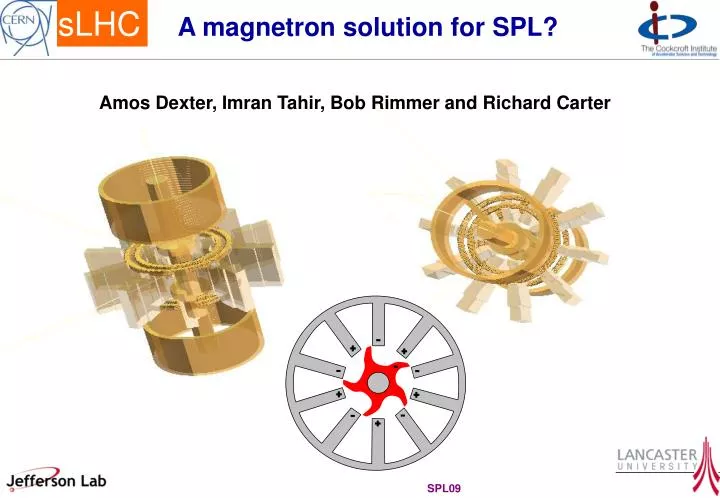
A magnetron solution for SPL? Amos Dexter, Imran Tahir, Bob Rimmer and Richard Carter
The Reflection Amplifier Cavity Load Magnetron Circulator Injection Source • Linacs require accurate phase control • Phase control requires an amplifier • Magnetrons can be operated as reflection amplifiers Compared to Klystrons, in general Magnetrons - are smaller - more efficient - can use permanent magnets (at 704 MHz) - utilise lower d.c. voltage but higher current - are easier to manufacture Consequently they are much cheaper topurchase and operate J. Kline “The magnetron as a negative-resistance amplifier,” IRE Transactions on Electron Devices, vol. ED-8, Nov 1961 H.L. Thal and R.G. Lock, “Locking of magnetrons by an injected r.f. signal”, IEEE Trans. MTT, vol. 13, 1965
Reflection Amplifier Controllability 0o towards magnetron Arcing Moding 900 W 800 W 700 W VSWR 6 2 3 4 90o 270o +5MHz +2.5MHz -5MHz +0MHz -2.5MHz 180o • Phase of output follows the phase of the input signal • Phase shift through magnetron depends on difference between input frequency and the magnetrons natural frequency • Output power has minimal dependence on input signal power • Phase shift through magnetron depends on input signal power • There is a time constant associated with the output phase following the input phase • Magnetron frequency and output vary together as a consequence of • Varying the magnetic field • Varying the anode current (pushing) • Varying the reflected power (pulling) 915MHz 916MHz Anode Voltage 10kW 20kW 30kW 40kW 3.00A 12.0 kV 11.5 kV 2.92A Power supply load line 2.85A 11.0 kV 2.78A 10.5 kV 2.70A Magnetic field coil current 10.0 kV 1 2 3 4 5 Anode Current Amps
Magnetrons for Accelerators Single magnetrons 2.856 GHz, 5 MW, 3ms pulse, 200 Hz repetition are used to power linacs for medical and security applications. Multiple magnetrons have been considered for high energy normal conducting linacs but the injection power needed for an unstabilised magnetron made it uncompetitive with a Klystron. Overett, T.; Bowles, E.; Remsen, D. B.; Smith, R. E., III; Thomas, G. E. “ Phase Locked Magnetrons as Accelerator RF Sources” PAC 1987 Benford J., Sze H., Woo W., Smith R., and Harteneck B., “Phase locking of relativistic magnetrons” Phys. Rev.Lett., vol. 62, no. 4, pp. 969, 1989. Treado T. A., Hansen T. A., and Jenkins D.J. “Power-combining and injection locking magnetrons for accelerator applications,” Proc IEEE Particle Accelerator Conf., San Francisco, CA 1991. Chen, S. C.; Bekefi, G.; Temkin, R. J. “ Injection Locking of a Long-Pulse Relativistic Magnetron” PAC 1991 Treado, T. A.; Brown, P. D.; Hansen, T. A.; Aiguier, D. J. “ Phase locking of two long-pulse, high-power magnetrons” , IEEE Trans. Plasma Science, vol 22, p616-625, 1994 Treado, Todd A.; Brown, Paul D., Aiguier, Darrell “New experimental results at long pulse and high repetition rate, from Varian's phase-locked magnetron array program” Proceedings Intense Microwave Pulses, SPIE vol. 1872, July 1993 Courtesy of e2v
Adler’s Equation for Injection Locking J.C. Slater “The Phasing of Magnetrons” MIT Technical Report 35, 1947 Shien Chi Chen “Growth and frequency Pushing effects in Relativistic Magnetron Phase – Locking”, IEEE Trans. on Plasma Science Vol. 18 No 3. June 1990. The basic circuit model for the phased locked magnetron is the same as for a cavity Injection Load impedance includes pulling effects. Negative impedance to represent magnetron spokes excitation of the anode. Includes static pushing effects. -ZS C Zw L R To get Adler’s equation set to give
Solution of Adler’s Equation Like for small y hence phase stabilises to a constant offset womagnetron ang. oscillation frequency without injection winjinjection angular frequency yphase shift between injection input and magnetron output Vinj /RFequivalent circuit voltage for injection signal / RF output Adler’s equation predicts that :- if wo = withen y→ 0 if wo close to withen y→ a fixed value (i.e. when sin y < 1 then locking occurs) if wofar fromwithen y→ no locking unless Vinj is large Steady state If the natural frequency of the magnetron is fluctuating then the phase y will be fluctuating. High frequency phase jitter will be filtered by a superconducting the cavity Advancing or retarding the injection signal allows low frequency jitter to be cancelled and the magnetron phase or the cavity phase to be maintained with respect to a reference signal.
Power Needed for Injection Locking The minimum locking power is given when sin y = 1 PRF is output power QL refers to the loaded magnetron. Pushing For our 2.45 GHz cooker magnetron (fi –fo) due to ripple ~ 2 MHz (fi –fo) due to temperature fluctuation > 5 MHz This is big hence must reduce fi – fo ( can do this dynamically using the pushing curve) ~ 400 ns ~ 1000 RF cycles Time response ~
Amplifier Requirement to Drive S.C. Cavity forward wave amplitude=F R1 L1 input waveguide C1 impedance transformer waveguide impedence =Zext L2 C2 R2 A full system model assists in understanding amplifier requirement equivalent electrical circuit for excitation of two cavity modes resulting differential equation for N modes ( Numerically solve envelope equations ) conversion from circuit parameters to cavity parameters • Microphonics cause wi to vary with time • Beamloading causes V to jump when a bunch passes through • The amplitude and phase of F depend on the controller, the amplifier characteristics and the coupler temperature
Amplifier action for SPL cavity - case 1 Plausible parameters Drive frequency in GHz = 0.704 GHz Centre cavity frequency in GHz = 0.704 GHz Number of cavity modes included = 1 Cavity Q factor = 1.0 E+09 External Q factor = 4.0 E+06 Cavity R over Q = 100 ohms Energy set point = 21.8 J Amplitude set point = 4.8792 MV Max Amplifier Power per cell = 59 kW Max voltage set point (no beam) = 13.740 MV Target fill time = 9.0E-04 s Cycle number for beam arrival = 568000 Maximum bunch phase jitter = 0.000 deg Bunch charge (ILC=3.2 nC) = 0.057 nC RF cycles between bunches = 2.0 Bunch train length = 1.2 ms Cavity frequency shift from microphonics = 60 Hz Cavity vibration frequency = 200 Hz Phase measurement error(degrees) = 0.000 deg Fractional err in amplitude measurement = 0.0000 Time delay (latency) for control system = 1.0E-06 s Control update interval = 1.0E-06 s Gain constant for controller = 0.55 Beam arrival real feedforward term = 0.50E+10 Beam arrival imag feedforward term = 0.13E+10 Amplifier bandwidth = 1.0E+06 Measurement filter bandwidth = 5.0E+05 In pulse rms phase err = 0.01909 deg In pulse rms amplitude err = 0.02998 % • Fill at almost full power • PI control plus simple feed forward when pulse arrives • Drive power and drive phase depends on cavity frequency offset caused by microphonics and Lorentz detuning
Phase and amplitude control – case 1 Filling at almost full power may give poor phase accuracy at start of bunch train In pulse rms phase err = 0.01909 deg In pulse rms amplitude err = 0.02998 %
Amplifier action for SPL cavity - case 2 Plausible parameters • Reduce fill rate as cavity approaches set point, the control system can then fix the phase error. • PI control plus simple feed forward when pulse arrives Drive frequency in GHz = 0.704 GHz Centre cavity frequency in GHz = 0.704 GHz Number of cavity modes included = 1 Cavity Q factor = 1.0 E+09 External Q factor = 4.0 E+06 Cavity R over Q = 100 ohms Energy set point = 21.8 J Amplitude set point = 4.8792 MV Max Amplifier Power per cell = 59 kW Max voltage set point (no beam) = 13.740 MV Target fill time = 10.0E-04 s Cycle number for beam arrival = 750000 Maximum bunch phase jitter = 0.000 deg Bunch charge (ILC=3.2 nC) = 0.057 nC RF cycles between bunches = 2.0 Bunch train length = 1.2 ms Cavity frequency shift from microphonics = 60 Hz Cavity vibration frequency = 200 Hz Phase measurement error(degrees) = 0.000 deg Fractional err in amplitude measurement = 0.0000 Time delay (latency) for control system = 1.0E-06 s Control update interval = 1.0E-06 s Gain constant for controller = 0.55 Beam arrival real feedforward term = 0.50E+10 Beam arrival imag feedforward term = 0.13E+10 Amplifier bandwidth = 1.0E+06 Measurement filter bandwidth = 5.0E+05 In pulse rms phase err = 0.01953 deg In pulse rms amplitude err = 0.00854 %
Phase and amplitude control – case 2 Phase correct at start of bunch train In pulse rms phase err = 0.01953 deg Note that microphonics start with same phase as before but as the bunch arrives later the cavity frequency offset is greater and the resultant phase error is greater despite the better start. In pulse rms amplitude err = 0.00854 %
Layout using one magnetron per cavity Permits fast phase control but only slow, full range amplitude control A substantial development program would be required for a 704 MHz, 880 kW long pulse magnetron Cavity Standard Modulator 880 kW Magnetron Load 4 Port Circulator Pulse to pulse amplitude can be varied Slow tuner LLRF ~ -13 dB to -17 dB needed for locking i.e. between 18 kW and 44kW hence between 42 kW and 16 kW available for fast amplitude control 60 kW IOT Could fill cavity with IOT then pulse magnetron when beam arrives
Layout using two magnetrons per cavity 440 kW Magnetron 440 kW Magnetron 440 W 440 W Permits fast full range phase and amplitude control Phasor diagram output of magnetron 1 output of magnetron 2 Cavity combiner / magic tee Advanced Modulator Advanced Modulator Load Fast magnetron tune by varying output current Fast magnetron tune by varying output current ~ -30 dB needed for locking LLRF 440 kW Magnetron design is less demanding than 880 kW design reducing cost per kW, and increasing lifetime and reliability.
Magnetron Size air cooling for cathode water cooling for anode dg Magnet dm hm If magnetron design is similar to industrial design with similar tolerances and can be made on same production line then cost may not be much more air cooling input for dome
Experiments at Lancaster Double Balance Mixer Oscilloscope 2 Stub Tuner 2 Loop Coupler 3 Stub Tuner 1 Water Load Loop Coupler Circulator 1 10 Vane Magnetron Water Load 1W Amplifier Circulator 2 C3 Load Power supply ripple IQ Modulator (Amplitude & phase shifter) D/A Oscilloscope A/D D/A Magnetron phase no LLRF DSP LP Filter 8 kHz cut-off Digital Phase Detector 1.3GHz D/A ÷ M ÷ M pk-pk 26o High Voltage Transformer Magnetron phase with LLRF pk-pk 1.2o Micro-Controller 40kHz Chopper Frequency Divider / N 2.3 - 2.6 GHz PLL Oscillator ADF4113 + VCO 10 MHz TCXO 1ppm Pulse Width Modulator SG 2525 Divider / R 1.5 kW Power Supply Phase - Freq Detector & Charge Pump Loop Filter 325 V DC + 5% 100 Hz ripple ADF 4113
Experiments at Lancaster 0 dBm RBW = 100Hz Span = 100 kHz Centre = 2.44998488 GHz -50 dBm -100 dBm +50 kHz -50 kHz Tahir I., Dexter A.C and Carter R.G. “Noise Performance of Frequency and Phase Locked CW Magnetrons operated as current controlled oscillators”, IEEE Trans. Elec. Dev,vol 52, no 9, 2005, pp2096-2130 Tahir I., Dexter A.C and Carter R.G., “Frequency and Phase Modulation Performance on an Injection-Locked CW Magnetron”, IEEE Trans. Elec. Dev,vol. 53, no 7, 2006, pp1721-1729 Phase shift keying the magnetron Lancaster has successfully demonstrated the injection locking of a cooker magnetron with as little as -40 dB injection power by fine control the anode current to compensate shifts in the natural frequency of the magnetron. Locked spectral output
Way Forward • Commission the development of a 704MHz Magnetron (440kW) • Procure standard modulator • Set up test station with IOT as drive amplifier • Understand locking characteristics of new magnetron • Commission advanced modulator with in-pulse current control • Establish minimum locking power • Establish two magnetron test stand • Develop LLRF for simultaneous phase and amplitude control Demonstration of CW 2.45 GHz magnetron driving a specially manufactured superconducting cavity at JLab due later this month should stimulate more interest.