Chapter 14: Activity Diagrams
CS 426/CPE 426 Senior Projects. Chapter 14: Activity Diagrams. February 25, 2014 [ Arlow and Neustadt , 2005] . University of Nevada, Reno Department of Computer Science & Engineering. Outline. Activity diagrams Introduction Activities Nodes Action nodes Control nodes

Chapter 14: Activity Diagrams
E N D
Presentation Transcript
CS 426/CPE 426 Senior Projects Chapter 14: Activity Diagrams February 25, 2014 [Arlow and Neustadt, 2005] University of Nevada, Reno Department of Computer Science & Engineering
Outline • Activity diagrams • Introduction • Activities • Nodes • Action nodes • Control nodes • Object nodes • Activity parameters • Pins Activity diagrams
Introduction: Chapter roadmap Activity diagrams
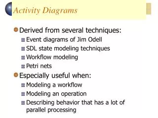
Introduction: What are activity diagrams? • Activity diagrams: • A form of “object-oriented flowcharts” • In UML 1 they were special cases of state machines; in UML 2 they have new semantics, based on Petri Nets • Greater flexibility to model different types of flow • Clearer distinction between activity diagrams and state machines • Attached to modeling elements to describe behavior • Typically attached to use cases, classes, components, interfaces, and operations • Can also be used to model business processes and workflows Activity diagrams
Introduction: Where are activity diagrams used? • Commonly used in: • Analysis • To model the flow of a use case • To model the flow between use cases • Design • To model details of an operation • To model details of an algorithm • Business modeling • To model a business process • As always in modeling, it is important to keep them simple and understandable by their intended audience Activity diagrams
Activities ***** • Activity diagrams are networks of nodesconnected by edges • Nodes • Action nodes – atomic units of work within the activity • Control nodes – control the flow through the activity • Object nodes – represent objects used in the activity • Edges • Control flows – depict the flow of control through activity • Object flows – depict the flow of objects through activity Activity diagrams
* Activities **** • Activities and actions can have pre- and post-conditions • Tokens (part of semantics but not shown graphically) abstractly flow in the network and can represent: • The flow of control • An object • Some data • A token moves from a source node to a target node across an edge depending on: • Source node post-conditions • Edge guard conditions • Target node preconditions Activity diagrams
** Activities *** • Example of an activity (“send letter”), Fig. 14.2 [Arlow & Neustadt 2005] Activity diagrams
*** Activities ** • Activity diagrams can model use cases as a series of actions. Example: Fig. 14.3 and Fig. 14.4 [Arlow & Neustadt 2005] Activity diagrams
**** Activities * • Activity diagrams have semantics based on Petri Nets • They model behavior using the token game • Tokens move through the network subject to conditions • Object nodes represent objects flowing around the system • Example of flow of control token, Fig. 14.5 [Arlow & Neustadt 2005] Activity diagrams
***** Activities • Activity diagrams can be divided in partitions (swimlanes) using vertical, horizontal, or curved lines. Example, Fig. 14.6 [Arlow & Neustadt 2005] Activity diagrams
Action nodes **** • Action nodes execute when: • There are tokens present at all their input nodes AND • The input tokens satisfy all action node’s local preconditions • Fig. 14.9 [Arlow & Neustadt 2005] Activity diagrams
* Action nodes *** • After execution, the local postconditions are checked; if all are satisfied, the node simultaneously offers tokens to all its output edges (this is an implicit fork that may give rise to many flows) • Naming convention, Fig. 14.10 [Arlow & Neustadt 2005] Activity diagrams
** Action nodes ** • Types of action nodes, Table. 14.1 [Arlow & Neustadt 2005] Activity diagrams
*** Action nodes * • A call action node invokes an activity, behavior, or operation, Fig. 14.11 [Arlow & Neustadt 2005] Activity diagrams
**** Action nodes • An accept time event action node responds to time, Fig. 14.12 and Fig. 14.13 [Arlow & Neustadt 2005] Activity diagrams
Control nodes ** • Control nodes manage the flow of control within an activity • Table 14.2 [Arlow & Neustadt 2005] shows the types of control nodes Activity diagrams
* Control nodes* • Examples of decision and merge nodes, Fig. 14.14 and Fig 14.15 [Arlow & Neustadt 2005] Activity diagrams
** Control nodes • Examples of join and fork nodes, Fig. 14.17 [Arlow & Neustadt 2005] Activity diagrams
Object nodes** • Object nodes indicate that instances of a particular classifier are available at a specific point in the activity • They are labeled with the name of the classifier and represent instances of that classifier or its subclasses • The input and output edges are object flows • Object flows are special types of flow that describe movement of objects within the activity • The objects are created and consumed by action nodes • When an object node receives an object token on one of its input edges, it offers this token to all its output edges, which compete for the token. Activity diagrams
* Object nodes* • Object node notation and their buffer semantics: Figs. 14. 18, 14.20 and 14.21 [Arlow & Neustadt 2005]. Object nodes act as buffers – places in the activity diagram where object tokens can reside while waiting to be accepted by other nodes (via edges). Activity diagrams
** Object nodes • Examples of using object nodes: Figs. 14. 19 and 14.22 [Arlow & Neustadt 2005]. Note that object nodes can represent objects in particular states. Activity diagrams
Activity parameters • Activities can have object nodes to provide inputs and outputs, Fig. 14. 23 [Arlow & Neustadt 2005]. Activity diagrams
Pins • A pin is an object node that represents an input to or output from an action node. Pins can simplify activity diagrams that use many object nodes. Example: Figs. 14. 23 and 14. 25 [Arlow & Neustadt 2005]. Activity diagrams