Download
1 / 48
480 likes | 765 Vues
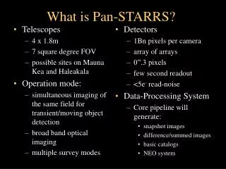
Telescopes 4 x 1.8m 7 square degree FOV possible sites on Mauna Kea and Haleakala Operation mode: simultaneous imaging of the same field for transient/moving object detection broad band optical imaging multiple survey modes. Detectors 1Bn pixels per camera array of arrays 0”.3 pixels

E N D
Telescopes 4 x 1.8m 7 square degree FOV possible sites on Mauna Kea and Haleakala Operation mode: simultaneous imaging of the same field for transient/moving object detection broad band optical imaging multiple survey modes Detectors 1Bn pixels per camera array of arrays 0”.3 pixels few second readout <5e- read-noise Data-Processing System Core pipeline will generate: snapshot images difference/summed images basic catalogs NEO system What is Pan-STARRS?
Performance Summary • Sensitivity (assuming 0.6” seeing) • T(R=24) = 58s • T(V=24.4) = 67s • T(R+V=24) = 31s • 30s exposure -> 6000 sq deg / night • Sky noise • 7e/s/pixel from sky (R+V) • Read noise ~2-3e is negligible for t >~ 20s • Astrometry • Sigma=0”.07 (FWHM/0”.6) / (SN/5) • Systematics limited by atmosphere
Small vs Large Apertures • Why size matters: • small telescopes are cheaper for given collecting area • CCD costs scale with detector area (not Npixels) • Optimal design matches seeing to CCD resolution • rapid construction and low risk • Fast guiding for enhanced image quality • Low environmental impact
Trends • Moore’s Law growth in CCD capabilities • Gigapixel arrays on the horizon • Improvements in computing and storage will track growth in data volume • Investment in software is critical, and growing • Future dominated by detector improvements Total area of 3m+ telescopes in the world in m2, total number of CCD pixels in Megapix, as a function of time. Growth over 25 years is a factor of 30 in glass, 3000 in pixels.
For (D ~ 4 r0) ~35% of light is in a single bright speckle • guiding at ~10Hz gives PSF with diffraction limited core • “tip-tilt” on large apertures is relatively ineffective D = 1.5m D = 8m D=4m
Detector Details – Orthogonal Transfer • Orthogonal Transfer • remove image motion • high speed (few usec) Normal guiding (0.73”) OT tracking (0.50”)
File : C:\ZEMAX\panstars\PS-prelim-9.ZMX Title: Pan-STARRS preliminary design review Date : TUE DEC 9 2003 SURFACE DATA SUMMARY: Surf Comment Radius Thickness Glass Diameter Conic r**2 r**4 r**6 6 Primary -7850 -2257.85 MIRROR 1800 -1.52934 2.24e-21 7 Secondary -6658 2057.85 MIRROR 900 -18.6695 4.68e-19 9 LENS-1A 994.5 60 F_SILICA 640 0 10 LENS-1B 1732.7 10 640 0 11 LENS-2A 801.7 45 F_SILICA 620 0 12 LENS-2B 540.0 815 620 0 13 FILTER-A Infin 20 F_SILICA 530 0 14 FILTER-B Infin 100 530 0 15 LENS-3A -1928.5 50 F_SILICA 520 0 4.02e-10 1.51e-15 16 LENS-3B -1790.1 198.07 520 0 IMA CCD-ARRAY Infin 500 0
Performance in U and Y • Optical Performance deteriorates at extreme ends of the optical region • Using a curved filter helps by giving extra refractive power
Ghost Image Analysis • Pupil ghosts • Image ghosts
Fabrication of the aspheric Optics • The asphericity of the mirrors is within established fabrication capability. • Dewar window is an order of magnitude less aspheric than the Sloan window ( 1 mm vs. 8mm)
Listing of surface sag File : C:\ZEMAX\panstars\PS-prelim-9.ZMX Title: Pan-STARRS rounded Date : MON NOV 24 2003 Units are Millimeters. Semi diameter of surface 6: 9.000000E+002. Best Fit Sphere curvature : -1.269040E-004. Best Fit Sphere radius : -7.879973E+003. Best Fit Sphere residual : 2.979204E-002. (rms) Y-coord Sag BFS Sag Deviation Remove 0.0E+000 0.00000E+000 0.00000E+000 0.00000E+000 6.31004E-002 5.0E+001 -1.59234E-001 -1.58631E-001 6.03222E-004 6.37036E-002 1.0E+002 -6.36929E-001 -6.34545E-001 2.38346E-003 6.54839E-002 1.5E+002 -1.43305E+000 -1.42779E+000 5.25245E-003 6.83528E-002 2.0E+002 -2.54755E+000 -2.53848E+000 9.06295E-003 7.21633E-002 2.5E+002 -3.98035E+000 -3.96674E+000 1.36087E-002 7.67091E-002 3.0E+002 -5.73137E+000 -5.71275E+000 1.86243E-002 8.17247E-002 3.5E+002 -7.80049E+000 -7.77670E+000 2.37849E-002 8.68854E-002 4.0E+002 -1.01875E+001 -1.01588E+001 2.87063E-002 9.18067E-002 4.5E+002 -1.28924E+001 -1.28595E+001 3.29439E-002 9.60444E-002 5.0E+002 -1.59149E+001 -1.58790E+001 3.59936E-002 9.90940E-002 5.5E+002 -1.92549E+001 -1.92176E+001 3.72901E-002 1.00390E-001 6.0E+002 -2.29121E+001 -2.28759E+001 3.62077E-002 9.93081E-002 6.5E+002 -2.68862E+001 -2.68542E+001 3.20589E-002 9.51593E-002 7.0E+002 -3.11771E+001 -3.11530E+001 2.40945E-002 8.71949E-002 7.5E+002 -3.57844E+001 -3.57729E+001 1.15029E-002 7.46033E-002 8.0E+002 -4.07078E+001 -4.07144E+001 -6.59053E-003 5.65098E-002 8.5E+002 -4.59470E+001 -4.59782E+001 -3.11241E-002 3.19762E-002 9.0E+002 -5.15017E+001 -5.15648E+001 -6.31004E-002 0.00000E+000
Tolerance Analysis • Sensitivity analysis of alignment • Monte Carlo modeling
Wavefront Sensing and Telescope Collimation • Tests with OPTIC using a calcite block to make extrafocal images • OPTIC design has 0.5” disk at 4” separation • PS design could be as much as an 8” disk at 10” separation, enough for 50-100 resolution elements over pupil.
In/extra Focal Images for Pan-STARRS r = 1.6 deg, SS filter Extra Intra Extra – Intra Nominal intra- and extra focal images, 4.4” diameter pupil 100m secondary decenter 0.01 deg secondary tilt
Atmospheric Dispersion • In the broad Solar System filter, atmospheric dispersion dominates other aberration for zenith distances over 10 deg.
PSF Area vs. Air Mass dispersion seeing charge diffusion trailing loss pixel
A traditional ADC contains many additional air-glass surfaces and does not achieve acceptable image quality over the wide Pan-STARRS field. Therefore we did not seriously consider ADCs before PDR.
ADC The design chosen has a rotating prism between fixed lenses. This avoids the large rotary seal and presents less of an engineering challenge and schedule risk. • Refractive indices match at 656 nm • Zero deviation • No added glass/air interfaces • No large diameter rotating seals • Relaxed tolerances on the flat surfaces Maximum correction No correction Siloxane Fused silica
Design Pan-STARRS Final 2: ADC on maximum dispersion Note: Box is 5"x5"
At 75° zenith distance, the ADC fully corrects atmospheric dispersion
Telescope Studies • Vertex RSI, Richardson TX • Common alt-az • Common equatorial • EOST, Tucson AZ • Common alt-az • Independent alt-az • Independent equatorial
Schematic of EOS Ice Dome as PS1 Dome PS1EOS Ice Dome MAGNUM
Mauna Kea CFHT UKIRT
Conceptual Configurations for Pan-STARRS-4 in the UH 2.2 m telescope building