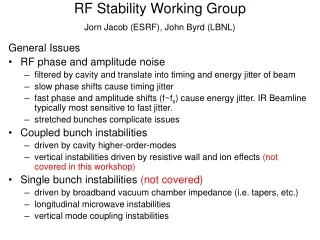
Stability of instruments at the ESRF
180 likes | 364 Vues
Stability of instruments at the ESRF. Y.Dabin Head of mechanical engineering ESRF - Grenoble . Vibration stability Thermal stability . With contribution of : Ph.Marion, L. Zhang, M.Lesourd,R.BAker, F.Pollack, JM.Dubuisson, JL.Marlat(Soleil) . ESRF Upgrade

Stability of instruments at the ESRF
E N D
Presentation Transcript
Stability of instruments at the ESRF Y.Dabin Head of mechanical engineering ESRF - Grenoble Vibration stability Thermal stability With contribution of : Ph.Marion, L. Zhang, M.Lesourd,R.BAker, F.Pollack, JM.Dubuisson, JL.Marlat(Soleil)
ESRF Upgrade CDR issues about technical difficulties 100% of BL raised The following issues: 1 Better optic quality 2 Preserve beam coherence 3 Operation with High heat load 4 Better Vibration Stability 5 Better Thermal stab. (drifts – 24H – uniform) 6 High Precision – High resolution
Support table...final design High stiffness…………………………….K Integrated damping (many frictions)…e Mass damping…………………………...M 1.5 m 4.5 m Transmission e K M 50 Frequency Motorised Z mvt Wide spread -> damping Horizontal Vib. Floor
Stability Minimum Degree of Freedom 2 Incidences 2 curvatures Should be Kept
1 mm FZP Magnified Image of the KB focal plane Effective pixel-size = 12 nm !Realtime visualisation possible The ultimate beam monitor FReLoNOptics KB X-ray Magnification = 56 FZP Peak to peak movements (through cross-correlation) 7 nm (vertical) 3 nm (horizontal) E = 9 keVKB aperture: 0.27 mm x 0.75 mmsecondary source open (0.5 mm)integration time: 1 s (full range FReLoN) W Ludwig, P Cloetens
New high flow rate air conditioning units ID22 – Nano-Imaging-Fluorescence Air renewal rate: 20 cycles / hour Vibrations from air flow reduced by porous ducts At present: 3 Nano-Hutches Next Upgrade : 15 Nano-Hutches
Typical focusing optic sensitivity Support table: Do we need antivib system under table support ? Spot size: 100 nm Stability : 10% d = 10nm q =0.1 m p =100 m source to optic Acceptable movements for the table sytem: Radial : Dz = d . p/q Acceptable Dz = ± 10 µm Dq Dz Angular : Dq = d /q Acceptable Dq = ± 0.1 µrd Angular vib.drifts much more critical than linear Transmitting floor vib. ( pv: 1µm ) seems acceptable
ID19 microfocusing experiment E = 24KeV F = 80 mm WD = 50 mm = 5.5 mrd Source ID19 Focus Focus detection Graded ML Aperture slits Curved graded ML Beam Dynamical bender
Vibrations influence XBPM and wavefront optimization camera Camera noise estimate = 3 nm Vib. origin to be analysed Radial / angular ? Courtesy of O.Hignette
Optic support from Desir beamline soleil Design: F.Pollack, JM.Dubuisson (Soleil )
Ultimate BPM All granite built-in movements ID 22 Nano-Imaging transmission µscope Present Spot size 80 nm
ID13 next Nano-focus End-station Service gantry Manipulation Alignment Mecartec tripod Cabling table assistance
Thermal stability minimizing the spectral with for the precision monochromator Precision mono ML mirrors (fixed exit ) 0.01 – 1 eV Monochromator 200 – 2000 eV bandwith High rate cooling Angular Radial Substrat supply
End show for the Wednesday working group