SOLEIL – ELTA /AREVA amplifier module at ESRF
440 likes | 1.2k Vues
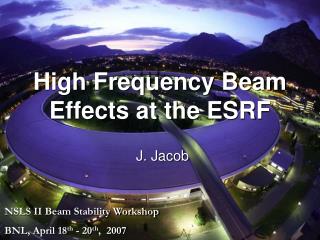
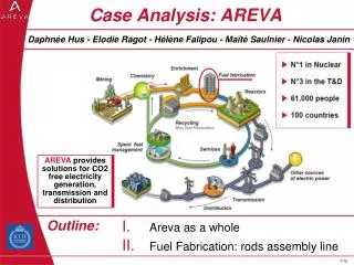
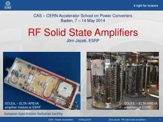
CAS – CERN Accelerator School on Power Converters Baden, 7 – 14 May 2014 RF Solid State Amplifiers Jörn Jacob, ESRF. SOLEIL – ELTA/AREVA amplifiers at ESRF. SOLEIL – ELTA /AREVA amplifier module at ESRF. Amplitude loop Phase loop Cavity tuning loop Cavity protection.

SOLEIL – ELTA /AREVA amplifier module at ESRF
E N D
Presentation Transcript
CAS – CERN Accelerator School on Power ConvertersBaden, 7 – 14 May 2014RF Solid State AmplifiersJörn Jacob, ESRF SOLEIL – ELTA/AREVA amplifiers at ESRF SOLEIL – ELTA /AREVA amplifier module at ESRF Jörn Jacob: RF solid state amplifiers
Amplitude loop • Phase loop • Cavity tuning loop • Cavity protection RF transmitters for accelerating cavities RF distribution Auxiliaries Pre- ampl. Power Amplifier Master Source LLRF Circulator Waveguide • Example ESRF Storage Ring: • ESRF 352 MHz RF system, before upgrade: • 5 MV re-acceleration/turn • 5 five-cell cavities provide 9 MV/turn • 300 kW copper loss in cavity walls • 200 mA electron beam in storage ring • 1000 kW beam power • RF power from 1.1 MW klystrons H Ibeam • Power Supply • Modulator E Load Accelerating Cavity Jörn Jacob: RF solid state amplifiers
Klys3 Klys1 Klys2 5-cell cavities: strong HOM ! Cell 5 Cav 1 & 2 Example ESRF: Recent RF upgrade Storage Ring • Replacement of Booster Klystron by: • 4 X 150 kW RF Solid State Amplifiers (SSA) from ELTA / AREVA: • In operation since March 2012 • 10 Hz pulses / 30 % average/peak power Teststand • 3 X 150 kW SSA from ELTA for the Storage Ring: • Powering 3 new HOM damped cavities on the storage ring • 1st & 2nd SSA in operation since October 2013 • 3rd SSA in operational since January 2014 150 kW 150 kW pulsed SY Cav 1 & 2 150 kW 150 kW Booster 150 kW 150 kW 150 kW ID ID Cell 25: Cav6 (Cav 5 removed) Cell 23: 3 HOM damped mono cell prototype cavities Jörn Jacob: RF solid state amplifiers
352 MHz 1.3 MW klystron Thales TH 2089 Klystrons in operation at ESRF • htyp= 62 % (DC to RF) • Gtyp = 42 dB Pin 100 W • Requires: • 100 kV, 20 A dc High Voltage Power Supply • with crowbar protection (ignitron, thyratron) • Modern alternative: IGBT switched PS • Auxilliary PS’s (modulation anode, filament, focusing coils, …) • High voltage X-ray shielding ! Klystron 1 MW power splitting between several cavities Jörn Jacob: RF solid state amplifiers
150 kW RF SSA for ESRF upgrade • Initially developed by SOLEIL • Transfer of technology to ELTA / AREVA Pair of push-pull transistors x 128 x 2 • 650 W RF module • DC to RF: = 68 to 70 % 75 kW coaxial power combiner tree 150 kW - 352.2 MHz Solid State Amplifier DC to RF: > 55 % at nominal power 7 such SSAs in operation at the ESRF! Jörn Jacob: RF solid state amplifiers
x 100…600 RF power sources for accelerating cavities PPM Ex: ESRF Klystron Pulsed Pulsed Klystrons MBK Diacrode CW Klystrons Tetrodes IOTs Ex: ESRF upgrade with SSAs CW or Average Transistor modules 160 to 1000W / unit Jörn Jacob: RF solid state amplifiers
Brief history of RF power amplification • Early 20th century: electronic vacuum tubes (triodes, tetrodes, …) • Typically limited to 1GHz due to finite electron drift time between electrodes • Still manufactured and in use today, kW’s at 1 GHz up to several 100 kW at 30 MHz forapplications from broadcast to accelerators(a small 3.5 ... 5 GHz triode for 2 kW pulses, 7.5 W average exists for radar applications) • 1940’s to 50’s: invention and development of vacuum tubes exploiting the electron drift time for high frequency applications (radars during 2nd world war), still in up-to-date for high power at higher frequencies • Klystrons 0.3 to 10 GHz, Power from 10 kW to 1.3 MW in CW and 45 MW in pulsed operation (TV transmitters, accelerators, radars) • IOT’s(mixture of klystron & triode) typically 90 kW at 500 MHz – 20 kW at 1.3 GHz (SDI in 1986,TV, accelerators) • Traveling wave tubes (TWT): broadband, 0.3 to 50 GHz, high efficiency (satellite and aviation transponders) • Magnetrons, narrow band, mostly oscillators, 1 to 10 GHz, high efficiency (radar, microwave ovens) • Gyrotron oscillators: high power millimeter waves, 30 to 100...150 GHz, typically 0.5…1 MW pulses of several seconds duration (still much R&D -> plasma heating for fusion, military applications) • 1950’s to 60’s: invention and spread of transistor technology, also in RF • Bipolar, MOSFET,… several 10 W, recently up to 1 kW per amplifier, maximum frequency about 1.5 GHz • RF Solid State Amplifiers (SSA) more and more used in broadcast applications, in particular in pulsed mode for digital modulation: 10..20 kW obtained by combining several RF modules • SOLEIL (2000-2007): pioneered high power 352 MHz MOSFET SSAs for accelerators: 40 kW for their booster, then 2 x 180 kW for their storage ring – combination of hundreds of 330 W LDMOSFET modules / 30 V drain voltage • ESRF: recent commissioning of 7 x 150 kW SSAs, delivered by ELTA/AREVA following technology transfer from SOLEIL – combination of 650 W modules / 6th generation LDMOSFET / 50 V drain voltage • Other accelerator labs, e.g.: 1.3 GHz / 10 kW SSAs at ELBE/Rossendorf, 500 MHz SSAs for LNLS, Sesame,… more and more up coming projects ESRF Example for this lecture Jörn Jacob: RF solid state amplifiers
Components of an RF SSA 1 2 Splitter by N N x RF modules e.g. 256 x 600 W 3 Power combiner x N SSA Drive Ampl(s) RF output e.g. 150 kW RF input 1 W @ 352.2 MHz Pre-Ampl. 4 Power Supply AC/DC power converter Transmitter controller / Remote control Local control and interlocking Cooling Water Jörn Jacob: RF solid state amplifiers
RF amplifier module: transistor SOLEIL / ELTA module for ESRF SSA • Pair of Push Pull MOSFET transistors in operated in class AB: • odd characteristic minimizes H2 harmonic [Ids(-Vgs) = -Ids(Vgs)] • SOLEIL: 30 V drain-source LDMOSFET from Polyfet 330 W • Today next generation 50 V LDMOSFET for 1 kW CW at 225 MHz from NXP or Freescale • For ESRF project: NXP / BLF578 650 W / module at 352 MHz Drain 1 Drain 2 Common Source Gate 1 Gate 2 Jörn Jacob: RF solid state amplifiers
RF power amplification - classes Class A: good linearity, But only maxtheor 50 % Ids Push-pull in class B: maxtheor 78.5 % t Ids1 -1/RL Vgs -1/RL Vds VOUT VIN VIN2 t Vgs1 Vds Vgs2 VIN1 VOUT Class B: maxtheor 78.5 % Ids -1/RL Ids2 Vgs Vds t • In fact push-pull in class AB for less distortion near zero crossing and lower harmonic content • Gate bias, 0.1 … 0.4 A/transistor without RF VOUT = sine wave thanks to resonant output circuit VOUT VIN
RF amplifier module: RF circuit Matching circuit Matching circuit Circulator Input balun Output balun Balun transformer: 1200 W Load Bias circuits Coaxial balun implementation Jörn Jacob: RF solid state amplifiers
RF module on SOLEIL/ELTA SSA for ESRF • Protection of RF module against reflected power by a circulator with 800 W load (SR: 1200 W) • No high power circulator after the power combiner ! • Input and output BALUN transformers with hand soldered coaxial lines • Individual shielding case per module • Temperature sensors on transistor socket and circulator load • Performance: 650 W, = 68 to 70 %, full reflection capability • RF module mounted on rear side of water cooled plate • Each transistor powered by one280 Vdc / 50 Vdc converter (2 dc/dc converters per RF module), installed with interface electronics on front side of water cooled plate • SSA powered with 280 Vdc, which is distributed to the dc/dc converters Jörn Jacob: RF solid state amplifiers
RF amplifier module: ESRF in house development ESRF fully planer design: • Printed circuit baluns • RF drain chokes replaced with “quarter wave” transmission lines. • Very few components left, all of them SMD and prone to automated manufacturing • Reduced fabrication costs Motorola patent unbalanced balanced • Still room for improvement • Ongoing R&D • Collaboration with Uppsala University for optimization of circuit board Jörn Jacob: RF solid state amplifiers
Components of RF SSA 1 2 Splitter by N N x RF modules e.g. 256 x 600 W 3 Power combiner x N SSA Drive Ampl(s) RF output e.g. 150 kW RF input 1 W @ 352.2 MHz Pre-Ampl. 4 Power Supply AC/DC power converter Transmitter controller / Remote control Local control and interlocking Cooling Water Jörn Jacob: RF solid state amplifiers
Power splitters for the RF drive distribution SOLEIL stripline splitters, using /4 transformers 50 50 50 50 50 N x splitter: Length = /4 Z = N x 50 50 Jörn Jacob: RF solid state amplifiers
Wilkinson splitter for the RF drive distribution 50 R = 50 50 50 R = 50 3 x splitter: Length = /4 Z = 3 x 50 R = 50 50 Addition of resistors to absorb differential signals without perturbing the common mode, thereby decoupling the connected outputs from each other Implemented on the prototype SSA under development at the ESRF Jörn Jacob: RF solid state amplifiers
Components of RF SSA 1 2 Splitter by N N x RF modules e.g. 256 x 600 W 3 Power combiner x N SSA Drive Ampl(s) RF output e.g. 150 kW RF input 1 W @ 352.2 MHz Pre-Ampl. 4 Power Supply AC/DC power converter Transmitter controller / Remote control Local control and interlocking Cooling Water Jörn Jacob: RF solid state amplifiers
Coaxialcombiner for SOLEIL/ELTA SSA at ESRF • EIA 9”3/16 for 160 kW (2 x 80 kW) x 2 150 kW SSA • 75 kW coaxial power combiner tree with • l/4 transformers like the splitters but used in reverse • Coaxial diameter adapted to power level: • EIA 1”5/8 for 6 kW power level (8 x 650 W) • EIA 6”1/8 for 40 kW (8 x 5.2 kW) • EIA 6”1/8 for 80 kW (2 x 40 kW) Each RF module is connected its 6 kW combiner by means of a 50 coaxial cable: 256 coaxial cables for 650 kW full reflection, with tight phase (length) tolerance Jörn Jacob: RF solid state amplifiers
ESRF - R&D of SSA using a cavity combiner * For 352.2 MHz ESRF application: • 6 rows x 22 Columns x 600 … 800 W per transistor module • 75 … 100 kW • More compact than coaxial combiners ßwaveguidenmodule x ßmodule >> 1 • Easy to tune if nmodule is varied • Substantial reduction of losses higher h H field Homogenous magnetic coupling of all input loops E field Strong capacitive coupling to the output waveguide Strongly loaded E010 resonance • Modest field strength • Cavity at atmospheric pressure • 1 dB - Bandwidth 0.5 … 1 MHz * Receives funding from the EU as work package WP7 of the FP7/ ESRFI/CRISP project Jörn Jacob: RF solid state amplifiers
ESRF-R&D of SSA using a cavity combiner • Direct coupling of RF modules to the cavity combiner: • No coaxial RF power line • Very few, sound connections • 6 RF modules are supported by a water cooled “wing” • The end plate of the wing is part of the cavity wall with built on coupling loops • One collective shielding per wing • Less than half the size of a 75 kW tower with coaxial combiner tree • Prototype with 18 RF modules x 700 W : • Successfully tested at 12.4 kW, = 63 % • 75 kW prototype with 22 wings in construction Jörn Jacob: RF solid state amplifiers
Components of RF SSA 1 2 Splitter by N N x RF modules e.g. 256 x 600 W 3 Power combiner x N SSA Drive Ampl(s) RF output e.g. 150 kW RF input 1 W @ 352.2 MHz Pre-Ampl. 4 Power Supply AC/DC power converter Transmitter controller / Remote control Local control and interlocking Cooling Water Jörn Jacob: RF solid state amplifiers
DC power requirement for ESRF 150 kW SSA from ELTA 90 % ! diff = dPrf/dPdc Pdc = Prf/Pdc • 400 Vac / 280 Vdc - 300 kW Power Converters • Built by ESRF Power Supply Group Jörn Jacob: RF solid state amplifiers
4 x 150 kW SSAs on ESRF booster • Booster Energy E cycled at 10 Hz (Sine wave from resonant magnet power supply system) • RF voltage requirement essentially to compensate synchrotron radiation loss: Vacc E4 (…+ other smaller terms) • Prfpeak = 600 kW • Pdcpeak 1100 kW • But: Pdcaverage 400 kW • 10 Hz power modulation • 3.2 F Anti-flicker filter at 280 Vdc • One common 400 kW – 400 Vac/280 Vdc power converter for 4 SSAs SSA provides almost a factor 3 power reduction as compared to former klystron transmitter With C = 3.2 F 3.2 F capacitor bank Jörn Jacob: RF solid state amplifiers
Planned ESRF booster upgrade With C = 3.2 F • Implementation of 4 Hz ramped DC magnet power supplies as alternative to 10 Hz resonant system: • Goal: easier bunch cleaning in the booster for future top up operation of the storage ring • Back up for 25 years old booster power supplies • 2 five-five cell RF cavities (two RF couplers each) 4 five-cell RF cavities (single RF coupler): • Same RF voltage with 1 SSA/cavity in fault out of 4 redundancy for frequent topping up • Alternatively: 40 % more RF voltage for same RF power as before • Consequence of new 4Hz waveform for the RF SSA’s: • Slight reduction of : Pdcaverage by 12 % • Twice as much Vdc ripple for 3.2 F Must double anti-flicker capacitances at 280 Vdc Jörn Jacob: RF solid state amplifiers
Main specifications and acceptance tests for RF Solid State Amplifiers example: ESRF 150 kW RF SSA from ELTA Jörn Jacob: RF solid state amplifiers
SSA gain/power, harmonics – CW pulsed operation • Specified efficiency easily met: • > 57 % at 150 kW = Pnom (spec: 55 %) • > 47 % at 100 kW = 2/3 Pnom (spec: 45 %) • Gain compression < 1 dB at Pnom = 150 kW • Gain curve and Pnom adjusted by means of load impedance on RF module • Avoid overdrive conditions • High peak drain voltage can damage the transistor • Overdrive protection interlock • Short pulses (20 ms) • Transient gain increase up to 1.3 dB • Risk of overdrive • Overdrive protection needs to be adjusted carefully • Requested redundancy operation reliability: • all specifications met with up to 2.5 % i.e. 6 RF modules OFF (becoming faulty during operation) • Power margin paid with efficiency: must be dimensioned carefully • Harmonics: H2 < -36 dBc, H3 < -50 dBc • Spurious sidebands / phasenoise: • < 68 dBc at 400 kHz (from DC/DC PS’s, harmless) • compare klystron -50 dBc from HVPS ripples at 600 Hz, 900 Hz, 1200 Hz, … moreover close to fsynchrotron 1 dB Gain diff = dPrf/dPdc = Prf/Pdc Efficiency / gain curve of 150 kW ELTA SSA at ESRF Jörn Jacob: RF solid state amplifiers
Adjustment of phase between 1st and 2nd 8x-Combiner stages when SSA matched: r = 0 1 module OFF experiences: High Preversecoming from other modules interference between 7 neighbours of same combiner and power from other combiners DFL Interference of reverse signals on the module 7 neighbours of same combiner ON: see only smallPreverse • DFL: proposed by SOLEIL DFL Jörn Jacob: RF solid state amplifiers
Adjustment of phase between 1st and 2nd 8x-Combiner stages Additional interference with reflection for mismatched operation: |r| = 1/3 (ESRF spec) • 1 module OFF: depending on DFL(and on reflection phase) the circulator load receives up to • Prevmax = 1500 W to 1700 W for worst DFL • Prevmax = 1100 W for best DFL • Active modules receive the remaining power: maximum of 400 W for best DFL • Successful implementation of best DFLand1200 W loads on the SSA for the SR, which are operated in CW • NB: not necessary on booster, operated in pulsed mode (800 W loads tested above 2000 W pulsed RF) 170 mm Jörn Jacob: RF solid state amplifiers
Transient reflections for pulsed cavity conditioning Measurement: P = |amplitude|2 HOM damped cavity at fres R/Q = 145 Qo = 32500 = 3.8 Computation: amplitude |r| = 1.5 Incident wave amplitude Reflected wave amplitude Amplitude [a.u.] Filtered reflection signal [RC=10s] t [s] • SSA tested with 20 s /150 kW pulses at full reflection • Fast interlock for Prefl > 150 kW • Interlock on low pass filtered signal for Prefl > 50 kW Jörn Jacob: RF solid state amplifiers
352 MHz 1.3 MW klystron Thales TH 2089 ConclusionShort comparison Klystron / SSA Jörn Jacob: RF solid state amplifiers
RF SSA as alternative to klystron: Pros & Cons • No High voltage (50 V instead of 100 kV) • No X-Ray shielding • 20 dB less phase noise • High modularity / Redundancy • SSA still operational with a few modules in fault (but not if driver module fails) • Increased reliability • More required space per kW than a tube, • But it is easier to precisely match the power to the requirement • Cavity combiners reduced SSA size • Durability / obsolescence: • Klystron or other tube: OK as long as a particular model is still manufactured, but problematic in case of obsolescence, development costs of new tubes too high for medium sized labs • SSA: shorter transistor product-lifetime, however guaranteed availability of comparable, possibly better transistors on the market requires careful follow up! • Easy maintenance, if there are sufficient spare parts available • Investment costs: • Still higher price per kW than comparable tube solutions • But SSA technology is progressing e.g. expected cost reduction with ESRF planar module design and compact cavity combiner • Prices for SSA components should sink • Prices for klystrons have strongly increased over the last decades • Low possession costs: • ESRF spec: Less than 0.7 % RF modules failing per year, most easy to repair • so far confirmed by short ESRF experience • SSA/tubes: Comparable efficiency, must be analyzed case by case • Reduced power consumption for pulsed systems (e.g. Booster), thanks to possible capacitive filtering of the DC voltage Jörn Jacob: RF solid state amplifiers
Acknowledgments • Tribute to Ti Ruanwho past away in March 2014. In the early 2000’s Ti Ruaninitiated the design and the implementation of high power SSA’s combining hundreds of transistors for larger accelerators. He is the father of the big SSA’s implemented at SOLEIL, ESRF and many other places around the world. • Many thanks also to the SOLEIL RF team, P. Marchand, R. Lopez, F. Ribeiro, to the ELTA team, mainly J.-P. Abadie and A. Cauhepe, and to my RF colleagues at the ESRF, in particular: J.-M. Mercier and M. Langlois. Their contributions constitute the backbone of this lecture. Ti Ruan at the 13th ESLS RF meeting at DESY in 2009 Jörn Jacob: RF solid state amplifiers
Thank you! Jörn Jacob: RF solid state amplifiers