Download
1 / 1
10 likes | 188 Vues
Commissioning of the ATLAS Pixel Detector Dr. Jens Weingarten, Exp. Physik IV, TU Dortmund on behalf of the ATLAS Pixel Collaboration. Threshold Adjustment. Commissioning in 2008. The ATLAS Pixel Detector. Discriminator thresholds can be adjusted individually (LSB~75e, dyn. range 7 bit)

E N D
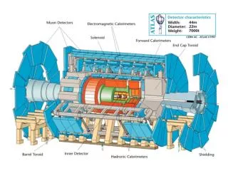
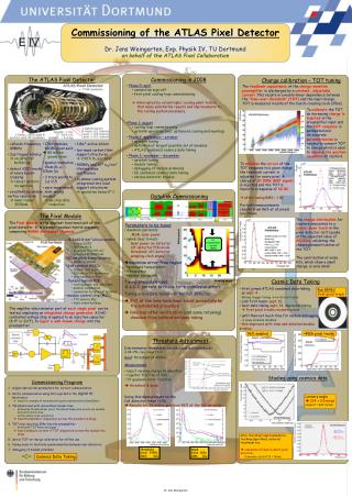
Commissioning of the ATLAS Pixel Detector Dr. Jens Weingarten, Exp. Physik IV, TU Dortmund on behalf of the ATLAS Pixel Collaboration Threshold Adjustment Commissioning in 2008 The ATLAS Pixel Detector Discriminator thresholds can be adjusted individually (LSB~75e, dyn. range 7 bit) Goal: threshold at 4000e • Phase 0: april • connection sign-off • first pixel cooling loop commissioning • interrupted by catastrophic cooling plant failure that made substantial repairs and improvements to the cooling system necessary • Phase 1: august • cooling loop commissioning • optolink operation (incl. optoboard cooling and heating) • Phase 2: september – october • optolink tuning • definition of largest possible set of modules • ATLAS combined cosmics data taking • Phase 3: november – december • optolink tuning • module tuning • debugging of module problems • ID combined cosmics data taking • various detector studies • Measurement • inject varying charge to amplifier • register fraction of hits • fit gaussian error-function • threshold & noise Doing this measurement on the full detector takes ~1.5h Results for 75 million pixels or 96% of the full detector • collision frequency 40MHz • 2us trigger latency on-detector buffering • detect 1000 tracks at every bunch- crossing robust pattern recognition • excellent secondary vertex resolution inner radius 50.5mm • 1744 modules, 46080 pixel each 80 million pixels total • spatial resolution 15um (R-f), 115um (z) • 3 track points to |h|=2.5 • zero-suppressed, semi-analog readout on-chip data reduction • 1.8m² active silicon • low-mass carbon fiber support structures 2.96% X0 per layer • 500kGy and 1015 neq/cm² lifetime dose and fluence • bi-phase cooling system integrated into local support structures operation below 0° C noise mean 165e RMS 30e threshold mean 3950e RMS 40e The Pixel Module Optolink Commissioning The Pixel Module is the smallest functional unit of the pixel detector. It is a sensor-readout hybrid assembly, comprising 46080 electronics channels. • 16.4x60.8 mm²silicon sensor • n+-in-n DOFZ • 250 um thick • pixel size 50x400 um² • operated at 150V bias • 50 um pitch bump-bonding • solder or indium • 2x8 readout ASICs • 18x160 cells each • 250 nm CMOS technology • wire-bonded to Flex • flexible kapton PCB • routing power and data lines • passive components • connection to external systems • module control chip (MCC) • TTC data to FEs • basic event-building • Parameters to be tuned • downlink(optional):MSR, laser power • uplink(less trivial): laser power on-detector; off-detector PIN diode threshold; off-detector sampling clock phase • maximize error-free region (EFR) • optoboard temperature • bitsequence • readout bandwidth • Tuning procedure uses • 0-1-0-1 pattern to check for transmission errors • Tuning procedure takes ~1h for full detector • 96% of the links have been tuned sucessfully by the automated procedure • links bad after verification (and some retuning) disabled from calibration/data taking Cosmic Data Taking PIN threshold • first joined ATLAS combined data taking on sept. 4. Wrong trigger timing no hits on tracks • LHC first beam: sept. 10 • next data taking sept. 14, improved timing first pixel tracks reconstructed • until then not much time for module debugging many modules disabled • this improved with time and detailed module studies Run 88463 first pixel track The amplifer-discriminator part of each single pixel can be tested, employing anintegrated charge generator. A DAC-controlled voltage step is applied to an injection capacitor (8 fF or 32fF), to inject a well-known charge into the preamplifier. 96% enabled ~450k pixel tracks sampling phase Commissioning Program Charge calibration – TOT tuning • Adjust optical link parameters for correct communication • Verify communication using hits injected in the digital FE-electronics • leads to a sample of modules with good communication (GoodOpto) • Threshold scan with and without sensor bias • determine threshold per pixel, threshold dispersion across one moduleand electronics noise • verify sensor bias connection • tune thresholds if dispersion across the module too large • TOT scan injecting 20ke into the preamplifier • determine TOT mean and sigma • tune feedback current if TOT dispersion across the module too large • derive TOT-vs-charge calibration for offline use • timing scans to facilitate synchronisation between sub-detectors • debugging of module problems The feedback capacitance of the charge-sensitive preamplifier is discharged by a constant, adjustable current. This results in a nearly linear dependence between the 'time-over-threshold' (TOT) and the input charge. TOT is measured in units of the bunch-crossing clock (25ns). Studies using cosmics data no transmission errors (EFR) To calibrate the TOT an increasing charge is injected in the preamplifier input and the TOT response is parameterized. An accurate parametrization is needed to convert TOT to charge which is used to improve the position resolution of clusters. Lorentz angle 214 ± 0.5 mrad (expect ~224 mrad) Cosmics Data Taking after the latest improvements in tracking algorithms, material treatment etc. resolution 23.4um in short pixel direction (reminder: pitch/√12 ~ 14um) To minimize the spread of the TOT response to a given charge, the feedback current is adjusted for every pixel. A charge of 20.000e (MIP signal) is injected and the TOT is tuned to a response of 30 BC. after tuning RMS < 1 BC For both measurements results from 96% of all pixels are shown. The charge distribution for clusters associated to a cosmic muon track in the pixel detector (left) peaks at the expected value of 20.000e, validating the chosen parametrization of the TOT. The contribution of noise hits, which show a small charge, is very small. Dr. Jens Weingarten