Download
1 / 24
250 likes | 470 Vues
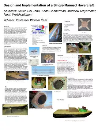
Control Design and Implementation of a Small-Scale Autonomous Hovercraft. University of Massachusetts Lowell James B. Francis College of Engineering Department of Mechanical Engineering Capstone. Ryan Mackay Joshua Bevan Nicholas Lutz Mario Stamatiou. Introduction.

E N D
Control Design and Implementation of a Small-Scale Autonomous Hovercraft University of Massachusetts Lowell James B. Francis College of Engineering Department of Mechanical Engineering Capstone Ryan Mackay Joshua Bevan Nicholas Lutz Mario Stamatiou
Introduction • Hovercrafts present a unique control challenge • It is an under-actuated system • 3 DOF of motion, 2 DOF of control • Requires optimization techniques to operate • The objective was to develop a robust control of the platform • Using GPS and inertial data provided by the IMU • Autonomously navigate between set waypoints
Overview • Hovercraft Platform • Theory • Mechanical Systems • APM • Design Methodology • Control Algorithm • Concepts • Inertial frame and body frame-dynamics of hovercraft • Inertial frame and body frame-kinematics of hovercraft • Set Point detection-turning • Setpoint detection-cruising • Implementation • Procedures and Methods for Design • Code Generation • Ground Control • Results and Analysis • Non-Optimized Track Test • Cross Track Error Optimized Track Test • Steering/Crosstrack Optimized & Box Test • Stability Dependence on Initial Conditions • Further Study • Special Thanks
Hovercraft Platform Theory • Lift Fan supplies air pressure filling the cavity and inflating the skirt • Once the air pressure equals the weight of the hovercraft the hover craft lifts and air escapes from the outlet ducts. • The escaping air creates a thin layer of air between the skirt and ground allowing the hovercraft to float over the ground.
Hovercraft Platform Mechanical Systems • Modified model hovercraft • Servo driven rudder system. • Single propeller thrust and lift fans. • Powered by 2000mAh NiMH and 3200mAh 4S LiPobatterys.
Hovercraft Platform Electronics • APM 2.5+ Assembled (Top entry) with 915Mhz (US) Telemetry Set • 3-axis gyro, accelerometer and magnetometer, along with a high-performance barometer • Onboard 4 MP Dataflash chip for automatic datalogging • Arduino Compatible APM • 3DR GPS uBlox LEA-6 • 5 Hz update rate • 25 x 25 x 4 mm ceramic patch antenna • 38 x 38 x 8.5 mm total size, 16.8 grams. GPS
Hovercraft Platform Design Methodology • Steering Mechanism • Rudder • More challenging control scheme due to parasitic thrust • Differential Thrust • Capability of turning in place, allowing more sophisticated control • Lift Mechanism • Flow Directing Duct • Uses a single fan, but requires thrust at all times during operation • Separate Lift Fan • Allows low thrust without losing lift • Microcontroller/ IMU • PX4 • More powerful processor • APM • More thoroughly documented source code and tutorials
Control Algorithm Concepts that were applied for development of control algorithm • Uses of Inertial frame and body frame for dynamic and kinematic analysis • The hovercraft is an under-actuated vehicle since there are three degrees of freedom and only two available control inputs. • Line of sight for detecting setpointswhile turning and cruising • Control theory application
Control Algorithm Inertial body frame dynamics East : North : forward direction on body-fixed frame ; :surge : right direction on body-fixed frame; : sway : angular velocity • Both Inertial frame and body-fixed frame are used for development of control algorithm • Inertial frame assumes a fixed origin. The Earth is assumed to be the origin of the inertial reference frame • Coordinates are defined in inertial reference frame • Force, moment velocity and acceleration are defined in body-fixed frame
Control Algorithm Inertial frame and body frame-kinematics • Re-direction of thrust from rudder creates and • generates a moment causing the hovercraft to turn; • Amount of thrust is expressed as a percentage relative to the maximum From Newton’s 2nd Law (assuming sway and kinetic friction are negligible) =>
Control Algorithm Set Point detection-turning : angle of hovercraft in inertial frame w.r.t line of setpoint ψ: angle of hovercraft in inertial frame w.r.t surge component (: setpoint coordinates ; ψr= • Hovercraft relies on line of sight to identify setpoint • The following condition has to be satisfied to identify setpoint where ε is a waypoint angle that bisects
Control Algorithm Setpoint detection-cruising • Once alignment is achieved the hovercraft translates until ( is reached. The distance ρ is given by: • A waypoint radius R is defined to let the board know when the hovercraft has reached the setpoint. • The point will have been reached under the condition
Control Algorithm Implemented Algorithm • The goal of the control algorithm is to adjust the amount of thrust and yaw while the hovercraft is approaching the set point For turning: T%= ∆%=-Kψeψ-Krr For cruising: T%=Kρρ-Kuu ∆%=-Kψ’eψ-Kr’r and so a single PID loop cannot be used, so =0,=0 • Control algorithm uses a combination of proportional control • Coefficients KρKu and can be accessed in the software of ArduRover
Implementation Procedures and Methods for Design
Implementation Methods for Design • 1|PID ρ_pid, u_pid, Ψ_pid, r_pid; • 2|if ( |bearing_error| < max angle for cruise ) • 3| Target_speed = cruise_speed + ρ_pid( distance_to_waypoint, kp=Kρ , ki=0, kd=0 ) • 4| Target_speed = Target_speed + ρ_pid( ground_speed, kp=Ku , ki=0, kd=0 ) • 5|else • 4| Target_speed = cruise_speed • 5|T% = calc_throttle( Target speed ) • 6|Limit T%min ≤ T% ≤ T%max • 7|∆% = Ψ_pid( sin(bearing_error), kp=Kψ , ki=0, kd=0 ) • 8|∆% = r_pid( omega.z, kp=Kr , ki=0, kd=0 ) • 9|∆% = (∆%)(cruise_speed/ground_speed) • Pseudo Code implementation of Control Algorithm • Differentiates between turning and cruising • Because in we use the sum of P’s rather than full PID’s. • Use generic PID function for generality
Implementation Generated Code
Implementation Generated Code
Implementation Ground Control
Results and Analysis Non-Optimized Track Test
Results and Analysis Cross-Track Error Optimization
Results and Analysis Steering/Crosstrack Optimization
Results and Analysis Stability Dependence on Initial Conditions
Further Study • Investigate terrain sensing • Infer terrain properties from inertial data and adjust lift in response • Explore path optimization • All waypoints are available at the start of flight • It should be possible to look forward in the path and plan actions beforehand • Develop controls to be used with a craft using differential thrust • Decoupling turning moment and thrust allows path optimization to be explored • Use sonar capabilities for obstacle avoidance • ArduRover software has the capability of doing obstacle avoidance • Adding a sonar module, autonomous navigation could be improved
Special Thanks We would like to acknowledge the efforts of Professor Raptis in acting as our capstone advisor. His contributions to our understanding of the theoretical and practical implementations of the control algorithm were invaluable. We would like to thank all the professors of the Mechanical Engineering Department for providing us the knowledge that was applied in successfully achieving the goal of this project. Additionally, we would like to thank RC Buyer’s Warehouse of Nashua, NH for providing advice on equipment selection.