Download
1 / 1
20 likes | 314 Vues
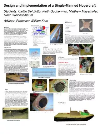
Design and Implementation of a Single-Manned Hovercraft Students: Caitlin Del Zotto, Keith Gooberman, Matthew Mayerhofer, Noah Weichselbaum Advisor: Professor William Keat. Lift System. The lift system is composed of four primary components. Lift Duct Lift Fan Lift Engine Engine Mount.

E N D
Design and Implementation of a Single-Manned Hovercraft Students: Caitlin Del Zotto, Keith Gooberman, Matthew Mayerhofer, Noah Weichselbaum Advisor: Professor William Keat Lift System • The lift system is composed of four primary components. • Lift Duct • Lift Fan • Lift Engine • Engine Mount Abstract The purpose of this project is to design and build a hovercraft that will carry one person over various terrains. It must have the ability to complete a maneuverability course, and have a top speed of at least 4 mph. It should have the ability to travel on smooth pavement, over grass, and over a parking lot curb. The finished product should cost less than $2300 (provided not all new material must be purchased) and must be completed by the end of winter term 2006. Our overall objective is to design a hovercraft which is capable of transporting one person. In order to do so we will need to create a platform which floats freely, even when loaded with hundreds of pounds of weight. This vehicle must be capable of running for extended periods of time. To accomplish this it must implement a fan to increase the pressure under the platform, as opposed to compressed air tanks. Once freely floating the hovercraft must be able to provide itself with enough thrust to propel forwards. This energy must also be provided with the use of a fan. After we have completed our design and created a moving hovercraft, we must successfully complete the multi-terrain course Lift Propeller Lift Fan The wooden lift propeller seen above was procured from Universal Hovercraft. This unfinished blade was the basis for the lift fan created for our hovercraft. The following procedure was followed for creation of the lift fan. First the lift fan was sanded down to the desired diameter of 34in which correlated to our lift engine operating at 3600rpm. Then a two-part epoxy, combined with microspheres to increase the adhesive surface area, was applied to the blades. Layers of 6oz fiberglass cloth were applied to the blades and were then saturated with the epoxy. Excess epoxy was removed and the fiberglass was molded to the props. This process was repeated twice producing the finished product seen below. Inserting Lift Duct prior to Foaming Lift Duct The lift duct was created from the diameter of our lift fan. Being that our lift fan was 34in,and there needed to be a 1/8in fan tip clearance on either side, the total inner diameter of the lift duct was 34-1/4in. The duct wall was created out of 1/8in plywood, liquid urethane foam with a density of 2-lb/ft^3, and fiberglass. Introduction The design requirements translate into a series of tests. First, the hovercraft must navigate through a course designed by William Keat. In order to determine a fair time in which the hovercraft must complete the course William Keat’s two year old son, Ian Keat, will perform a time trial. In this course the hovercraft must be able to travel over grass, concrete, gravel, and water. Second, our vehicle must be able to climb over a parking curb without bottoming out. Third, we must be able to drive this hovercraft up an incline of an angle of 15 degrees. A hovercraft can be decomposed into several subsystems. In our research we found the most important subsystems of the hovercraft are the lift and thrust systems. The lift system has two primary jobs. The first job is to create enough air pressure under the hull of the craft to lift it off the ground. This is done by using a lift fan with many blades and also keeping the blade tip clearance tight so that the amount of air lost between the duct and the blades is minimized. The second job is to replenish the amount of air lost. For a hovercraft to work properly, a certain amount of air is needed to create enough pressure to lift it. If this air lost, due to leakages and surface changes, is not replenished as quickly as it is lost, the craft will lose hover height. The “backbone” of the lift system is the skirt. The skirt must perform three key functions: It must contain the air supplied by the lift fan, it must be able to contour to the changing terrain and it must also offer some stability. The thrust system has one primary job and that is to create enough horizontal force to move the craft. The overall speed of the craft will be dependent on the size of the thrust fan and motor. Design of Cockpit Fiberglass process and finished project Lift Engine The lift engine was a 15.5hp vertical shaft engine that was attached directly to the propeller as can be seen below. End of fall term Final Design Lift Engine Mount The lift engine mount was designed similar to specifications supplied by Universal Hovercraft. The engine mount had to span over the 33” lift duct and attach to a truss built from 2”x4” on either side. The engine mount also had to sink the engine into the lift duct to ensure the largest pressure difference. The mount was designed using Solidworks and manufactured out of soft carbon steel by the Union College Machine Shop. Centering the lift fan was a trial and error process in which the team attached the motor and the fan and altered the location of the engine mount to accommodate the fan blades not dragging against the inside of the duct walls. Lift Duct- Before liquid foam wall was erected Design of Cockpit Lift Engine attached to propeller Lift Engine Mount (in Solidworks) Conclusions The safety of the driver of the hovercraft, as well as those that may be in the surrounding area is of the utmost concern. The driver of the hovercraft will be secured in the cockpit by means of a safety harness that will be attached to the seat. The driver of this vehicle will also be equipped with a helmet, life-jacket (the hovercraft may be over water and lifejackets are required by boating law), and earplugs (the noise produced by two large motors can be quite deafening). The engines on the hovercraft will both be equipped with kill switches that will be located in the cockpit in case the hovercraft happens to lose control. The fans that are attached to these engines will be safely housed in fiberglass ducts with filters over them to keep out debris and prevent human contact with the fan blades. Many aspects of manufacture could not be planned ahead, but instead had to be conquered one obstacle at a time. Together as a team, we successfully solved many problems that arose during the building process. Unfortunately, there were some complications at the factory where we ordered many of our parts. This caused a delay in the shipping of many very important materials, and therefore resulted in the thrust system to not be completed. Technically, a hovercraft is a platform that can essentially “float”. Therefore, we completed just that; a hovering platform. Platform prior to adding Skirt and Lift Duct Skirt A bag skirt was chosen for the final. Of all the skirts investigated, it is the lowest cost, least complex to manufacture, and is the most stable. The skirt will be constructed out of 1050 denier ballistic nylon that is coated in polyurethane. This is a very durable material that will withstand the rough treatment the skirt may face. The skirt material was cut in widths of 30” and fitted to the different sides of the craft. We used six separate pieces of skirt material, one for each side. Each piece was attached to the next using H-66 vinyl cement. On the bottom of the platform is a sequence of ½” x ½” pieces of wood following the outline of the craft but offset inwards from the platform edges. These pieces of wood are used to attach the skirt to the underbelly of the craft. We attached the skirt using a few hundred ¼” screws, spaced every three inches. As can be seen in the bottom view of the platform, these pieces overlap the lift duct. These pieces act as splitters in a sense. A small amount of air is used to blow up the bag while the majority of the air is used to pressurize hull. Lift Engine attached to engine mount Lift Engine Mount Final Product Bottom View of Platform with Lift Duct ready for Skirt to be Attached Right Side of Skirt- Fully Attached Hovercraft with cockpit, lift system, and skirt attached