MTA Instrumentaion
170 likes | 202 Vues
Explore the cutting-edge instrumentation and hardware at University of Illinois for LH2 absorber research. Learn about data collection, processing, and measurement hardware including FISO bus system, LakeShore 218 temperature monitor, and more. Discover the capabilities of IRM and PCI-MIO-16E-1 ADC and how Labview is used for user interface with external devices. Dive into the challenges of sensor calibration and data processing, highlighting the focus on high-resolution readings and sensor-specific calibration curves.

MTA Instrumentaion
E N D
Presentation Transcript
MTA Instrumentaion University of Illinois (UIUC) Debbie Errede Mike Haney Zack Conway Fermilab Robert Goodwin Mike Kucera Mike Shea Feb 22, 2003
What’s Going On? • Instrumentation • Hardware • Data Collection • Data Processing • Measurements
Hardware • In Urbana we have: • FISO bus system. • Fiber optic light conditioner. • LakeShore 218 temperature monitor. • Diode/resistive temperature sensor monitor. • IRM(Internet Rack Monitor) • Fancy ADC connected to the Fermilab Ethernet. • “Fast” ADC with 8 differential channels • PC card.
FISO BUS SYSTEMPart 1 • Currently we have 4 signal conditioners. • Can take data at 1kHz. • Room for 8 total(4 more) signal conditioners. • We have temperature, pressure, and strain gauges. • Each signal conditioner can illuminate a separate sensor.
FISO BUS SYSTEMPart 2 • Gauges are not certified below 250K. • The gauges have been used to 35K but never below(H. Kirk @ Brookhaven). • Working with FISO technologies Inc. to modify the internal calibration curves. • By mid-March we will be able to simulate many aspects of the LH2 absorber in Urbana for sensor testing.
LakeShore 218 Temperature Monitor • 8 channel temperature monitor. • Supports two sets of 4 channels. • Each set of channels can be calibrated for either diode or resistive temperature sensors. • 1.4K-325K temperature range for each channel. • Temperature resolution of ~10mK at 20K in a rad free environment. • Maximum data collection rate on all channels in 16 Hz.
IRM(Internet Rack Monitor) • IRM comes with: • 64 differential A-D input channels. • 8 bytes of digital I/O channels. • 8 bytes of D-A output channels. • Ethernet LAN interface.
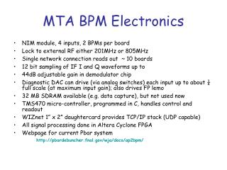
PCI-MIO-16E-1 ADC • 16 channel ADC(8 differential channels) • 12 bits per channel • 1.25 Msamples/s • Each ADC channel built into an IRM has a maximum operating rate of 100 ksamples/s. • Internal PC device.
Data Collection • All hardware can communicate with external devices. • The process repeats itself at regular intervals(15Hz???). • Using Labview as a user interface between the PC and the hardware. • Labview comes with built in functions supporting hardware communication: • GPIB, Serial, UDP, TCP/IP, ect.
Labview • Very modular • Each instrument has its own independent code. • Labview can run each instrument’s code concurrently. • Labview code is very easy to understand.
Collection Control • At this time: • One master configuration file. • All of the data will be saved to the PC’s hard drive. • There are size issues when writing to the IRM. • ~1kB every 66 milliseconds is the current goal. • What should be posted on the IRM?
IRM Data Collection • Operates repetitively at a constant rate. • In Urbana we are running at 12.5Hz. • Can definitely handle 15Hz operation. • Faster??? • Each cycle includes: • The revision of the analog and binary data tables. • Answering/generating messages for other IRMs, ACNET, our PC, ect….
IRMPart 2 • University of Illinois IRM: • Has room for 1000 virtual channels. • Can be upgraded to 2000 virtual channels. • All channels are ACNET compatible. • 2MB of free memory. • Not as structured as the channel data.
Data Processing • The PC can handle almost any data type sent to it at high rates. • The IRM • Refresh rate of data is limited. • Amount of data refreshed per cycle is limited. • Data must be formatted. • Each reading occupies 2 bytes of memory. • This leaves 65535 steps to record each data point.
IRM Data Processing • Take an ammeter. • Let’s say it needs to measure a current from 0 to 200mA. • So the maximum resolution the IRM data can have is: • 200mA/65535=0.0031mA • In other words • IRM Reading = (1/0.0031mA)*Current Hardware value.
Hardware Data • All sensor readings use different units. • Each sensor requires its own calibration curve. • The current plan: • Save the non-calibrated data to disk. • Post the adjusted data for ACNET.
Wrap up • U of I @ Urbana-Champaign is focusing on the data collection and hardware for the LH2 absorber. • The hardware works but sensor calibration remains a high priority.