Report from UWA
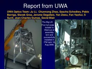
Report from UWA. UWA Optics Team: Ju Li, Chunnong Zhao, Sascha Schediwy, Pablo Barriga, Slavek Gras, Jerome Degallaix, Yan Zewu, Fan Yaohui, S Sunil, Jean-Charles Dumas, David Blair. The Big Lift:

Report from UWA
E N D
Presentation Transcript
Report from UWA UWA Optics Team: Ju Li, Chunnong Zhao, Sascha Schediwy, Pablo Barriga, Slavek Gras, Jerome Degallaix, Yan Zewu, Fan Yaohui, S Sunil, Jean-Charles Dumas, David Blair The Big Lift: First full scale isolator is lifted out of assembly tent and successfully installed in ITM tank 16 Aug 2006
Light Scattering in LIGO Fused Silica Sample • As arranged in last telecon Helena sent a sample of fused silica for UWA to measure light scattering in the bulk. • We have measured one plane using our ASM machine.(Automatic scattering measuring machine…tomography using single beams.) • Result: very high scattering…see next slide…74ppm/cm
Parametric Instability Studies at UWA • Quantifying PI taking into account as many uncertainties as possible. • Suppressing PI using ring damping • Suppressing PI using active feedback • Experimental studies at Gingin
Three new results on Parametric Instability Tilts and Spot Size: Both tilt fluctuations and spot size variations can tune PI. Tilt induced degeneracy breaking between HG and LG modes can introduce further unstable modes. Ring damper suppression of PI. Preliminary results for AdvLIGO with sapphire test masses (easiest case, fewer modes) show stable operating windows with 5% increased thermal noise, 2.3% degraded ns-ns inspiral performance. Enhanced optical spring effects allow short tranquiliser cavities for parametric instability control to use lower power and lower finesse.
Higher Order Modes Pablo Barriga Perfectly aligned cylindrically symmetric cavity with finite size mirrors it can only sustain LG modes. HG modes can be expressed as linear combinations of LG modes, but the frequencies are degenerate: no contribution to PI Tilt fluctuations break the degeneracy: additional modes potentially contribute to PI. We are quantifying this effect.
Spot Size Tuning Pablo Barriga Thermal lens induced changes in spot size will change the mode gap and the resonant conditions for Parametric Instabilities.(Edge effects) A change of 1% in the spot/mirror ratio produces typically ~30Hz change of frequency. Sufficient to cause significant parametric gain modulation.. Advanced LIGO
Frequency Gap Tilt Effects HG50 HG40 HG05 HG04 The frequency change will depend on the orientation of the mode profile in relation to the tilt. For PI only the frequency gap between TEM00 and HOM is significant. Therefore the frequency gap between fundamental and higher order modes will also depend on this relative orientation.
Frequency Shift for LG Modes of Order 4 Frequency change with ETM mirror tilt for modes of order 4 18400 18395 18390 Frequency (Hz) 18385 18380 18375 18370 0 200 400 600 800 1000 1200 Mirror tilt (nrad) LG04 LG12 LG20 HG40 HG31 HG22 Transverse mode frequency variation with mirror tilt. Frequency difference between fundamental mode and modes of order 4. HG40 LG20 LG12 HG31 HG22 LG04
Conclusion: Tilts and Spot Size • Effects are small and are unimportant assuming spot size is well controlled and tilts are within AdvLIGO specs…10nrad • However spot size is important in obtaining accurate estimates of PI
Ring Damper • We have done the ring damper modelling for sapphire because it involves fewer modes and we can get results in less time. • Fused silica now underway. • Choose to use a standard optical coating for the ring damper as it is a well understood vacuum compatible material.
Optical coating Optical Coating Strip Ring damper model • various positions, • different dimensions: • thickness • width • different properties: • -loss angle (thermal noise) -tantala/silica layers -loss freq. dependent Test mass radius r = 0.157m Thickness d = 0.13m
PI and Ring Damper calculation proceedure High resolution FEM model (half-plane symmetry model) with coatings calc freq and mode shape of all acoustic modes to 160kHz (coating has small effect on mode shape, frequency and mode effective mass. (some non-symmetric modes omitted) Low resolution FEM(full cylinder model with inertia relief) to calculate thermal noise as seen by Gaussian beam due to substrate and coatings losses. (confirmed no resolution induced errors) Use Matlab code eigenvalue method to calculate diffraction losses for different ROC configurations. Calculate optical mode shapes analytically corresponding to infinite mirror approximation Run Matlab Parametric Instability Code using optical modes to 9th order, to calculate overlap parameter as function of radius of curvature. Create histogram of number of unstable modes, R-values etc. Repeat for different ring dampers. Each ring damper is designed so that it increases the brownian thermal noise by a given percentage at 100Hz referred to the Brownian thermal noise for ROC of 2076km beam spot radius 6cm. Use bench code to estimate binary inspiral range. (Switch off residual gas and suspension TN and gravity gradient noise). Photothermal noise and quantum noise terms at default values in Bench Code.
Power recycling mirror /coating Comparison of R gain for different RoC, with PRM (red) and without PRM (blue) Effect of the coating losses on parametric gain
Parametric Instability control • Ring damper 3cm x 20microns, 5 x 10⁻³ loss angle sufficient to create stable windows (worst case model, no suppression of instability by arm imbalance). • Brownian thermal noise degraded 5%, inspiral range degraded 1.5%..see next slide stable windows
ALS, DTN=5% About 30% 0f phase space is instability free
NS/NS binary inspiral range vs. ETM RoC (ITM fixed) AdvLIGO Spot sizes 6.5,6.3 6.37,6.27 6.24,6.18 6.12,6.09 6.01,6.01 5.90,5.93 It seems that the NS/NS range degradation due to the ring damper remains constant for different RoC_ETM.
ALS with a ring vs AdvLIGO @ 2076 m ALS AdvLIGO 212.03Mpc (with strip) 178.17 Mpc (no strip) We are surprised that sapphire with ring damper is better than the Adv LIGO number we get from default settings of bench. It would be very useful have independent verification of these results!
Unstable - Instability ω0 ω0 ω0 ω0 – Ωm Ωm Stable – Cold Damping ω0 ω0 ω0 ω0 + Ωm Ωm Enhanced Optical SpringParametric Instability Sascha Schediwy - schediwy@physics.uwa.edu.au Frad StableUnstable
Enhanced Optical SpringParametric Instability fmech Sascha Schediwy - schediwy@physics.uwa.edu.au • Background information for next slide: • --Optical spring Q change arrises due to the phase lag introduced by a non-zero cavity storage time. • Next slide shows Q-1 vs. cavity offset for 10cm Nb cavity. • Cavity is locked with PDH feedback servo. • Servo uses analogue f-1 filter with corner frequency fc. • Servo electronics introduces phase lag. • Optical spring instability or damping enhanced ~20 times. Closed Loop TF’s Niobium resonator fmech = 750Hz
Sascha Schediwy - schediwy@physics.uwa.edu.au Measurement Theory Cold Damping Region -74deg -19deg no enhancement Unstable Region CriticallyUnstable Region Enhanced Optical SpringParametric Instability
Enhanced Optical SpringParametric Instability Sascha Schediwy - schediwy@physics.uwa.edu.au • Formulae to calculate the change in the quality factor Qnew’ for the enhanced optical spring fromkopt and the servo introduced phase lag θ: where: with and and • Above spring constant formulae derived from 1st principles and also from: Braginsky, V.B. and S.P. Vyatchanin,. Physical Letters A, 2002. 293: p. 228-234. Sheard, S. Gray, M. Mow-Lowry, C. and McClelland, D. Physical Review A, 2004 69: 051801(R).
Conclusion Short Optical Cavity Tranquiliser looks much more practical as strong optical damping can be achieved for relatively low finesse. Need to confirm noise performance Ring damper looks very promising but difficult to completely elliminate instability without serious noise price. Thermal tuning: spot size effects not a problem Need to repeat analysis for fused silica.
AL - IFO modeled IFO: Sapphire ETM/ITM: r = 0.16m d = 0.13m Spot size: w = 6.0cm arm length: L=4km diffraction loss (per bounce @ 2076m): 3.81ppm Unstable modes (R>=1): 380 Ring damper model (all TMs) : Strip width: 3 cm Strip thickness: 20µm Loss angle: chosen in such way that the ifo Brownain thermal noise @ 2076 would increase by 5%. Φ = 3.5909e-3 Brownian Noise at 2076 m (FEM result ): ITM ETM Coating 2.7242e-21 4.1503e-21 Substrate 1.4448e-21 1.4448e-21 Ring 1.2063e-21 1.2063e-21 Total 7.5304e-21 Coating info: ITM T=5% -> 8 layers of Ta2O5 +8 layers SiO2 ETM T=5ppm -> 18 layers of Ta2O5 +18 layers SiO2
Notes: • -100% , 90% and 75% corresponds to the coating TN. I assumed that future coating may be better than the present ones by these factors: used in the Bench code. • If Total Brownian TN @ 2076 m is equal 7.5304e-21 (without a strip) than by adding a strip with loss = 3.5909e-3 it causes 5% Brownian thermal noise degradation . • If Coating TN was reduced to 90% for both ITM and ETM mirrors than the strip with the same loss value as above would cause DT=~14.5%. If coating TN was 75% smaller than DT increases to ~32.3%. • According to NS/NS results (slide 3), inspiral range does not follow this pattern. This range would be only decrease by ~1.7% for all cases (0%,10%,25%). I’m not sure why it is so… maybe it’s due to the high thermoelastic noise? As seen in the slide 5 this noise is much higher than the strip one. If this is true, than silica test mass with much lower thermoelastic noise would be more susceptible to the strip noise (I think) • Slide 4 shows only NS/NS range for not reduced coating TN (100%).