Download
1 / 31
310 likes | 514 Vues
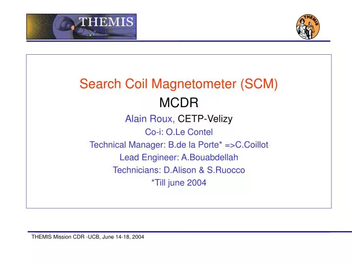
Search Coil Magnetometer (SCM) MCDR Alain Roux, CETP-Velizy Co-i: O.Le Contel Technical Manager: B.de la Porte* =>C.Coillot Lead Engineer: A.Bouabdellah Technicians: D.Alison & S.Ruocco *Till june 2004. Team re-organisation. Technical Manager: Bertrand de la Porte

E N D
Search Coil Magnetometer (SCM) MCDR Alain Roux, CETP-Velizy Co-i: O.Le Contel Technical Manager: B.de la Porte* =>C.Coillot Lead Engineer: A.Bouabdellah Technicians: D.Alison & S.Ruocco *Till june 2004
Team re-organisation • Technical Manager: Bertrand de la Porte • team management, general schedule • Lead engineer: Christophe Coillot • SCM support: design, manufacturing: • Sensors : design, manufacturing, tests, • PA: electrical design, tests procedures, EM&FM tests. • Sniffer design, manufact. & tests • Engineer: Abdel Bouabdellah • ICD&PAIP management, Vibration tests, • PA: PCB cabling, design of housing, • manufacturing, PA I/F. • Technician: Dominique Alison • PA/PCB design, • Manufacturing sensors, • I/F PA: design, manufact., tests • Technician: Sébastien Ruocco • Sniffer & tests: • Technical Manager: Christophe Coillot • team management, schedule. • SCM support: manufacturing, schedule, • Sensors : manufacturing, EM&FM tests, • PA: tests procedures, EM&FM AIT • Lead Engineer: Abdel Bouabdellah • ICD&PAIP management, Vibration tests, • PA: PCB cabling, manufacturing, PA I/F general schedule. Integrations. • Technician: Dominique Alison • PA/PCB design, • Manufacturing sensors, • EM&FM tests&integrations • Technician: Sébastien Ruocco • PA: FM tests. • Sensors: FM tests. • Integrations
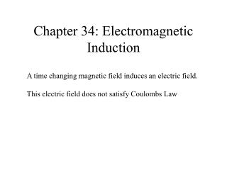
SensibilityEM (pT/sqrt(Hz) 10 1 0.1 0.01 0.001 1 10 100 1000 10000 Fréquency (Hz)
3-axis structure Design includes EPR remarks and numerical simulation results. Interface is completely defined (cf. P. Turin). EM structure delivered by GdTech to CETP: May 17th.
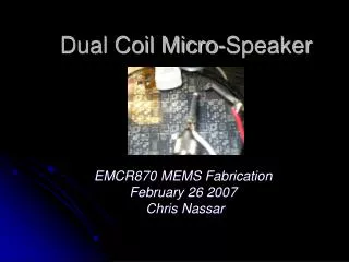
PA Design by 3D+ • Mechanical characteristics: • 2 amplification levels • 3 radiation shielding levels • Dimensions: 20 x 20 x 15 (mm) • Weight : 15 g Pre-Amplifier module
Operations • When ON, SCM is continuously measuring the magnetic field up to 4 kHz. • Once per orbit a calibration is run for 30 secs (default) • After 60 seconds, the Calibration is automatically turned off.
Test plans: PA cubes * Takes into account changes suggested during CDR peer review
Interface verification at UCB • An interface model has been built and sent to UCB to test I/F to IDPU . • Same Power, Command, analog output interfaces • Power and Cal Mode identification by LED • Cal Signal re-injected to the input • A signal generator can be connected to each input
I&T at UCB • Pre-integrations at UCB • After delivery to UCB (Incoming Inspection, Bench Test) • Sensor in the mu-metal box • Electrical Integration • Power ON and functionnal test • Validation can only be done by analysis of telemetry data
I&T at s/c level • Integration on the spacecraft • Mechanical Integration of the PA, connection to the boom harness • Sensor in the mu-metal box • Electrical Integration (bounding, isolation) • Power ON and functionnal test • Validation can only be done by analysis of telemetry data
SCM tests at s/c level: 1 Initial configuration: The sensor is inside the mu-metal box, connected to the PA via the boom harness Requirement: keep the sensor in the mu-metal box until all experiments are integrated in the spacecraft (mission operation test)
SCM tests at s/c level: 2 • WHAT CAN BE DONE WITH THE SENSOR IN THE MU-METAL BOX? • Verification of the labelling of axis (X,Y, Z) • (Re)-verification of the end-to-end calibration • Phase relation between the 3 components (for the waveforms) • Measure the conducted noise • SCM/EField timing reference [and inter-calibration]
SCM integr. at s/c level: 3 • SENSOR MOUNTED ON THE BOOM • PA saturated by the 50/60 Hz (except in an EMC chamber). • No measurement possible but a major failure would be detectable. • INSTALLATION OF THE MLI: preferably at the last moment, before s/c vibration tests.
EMC tests at s/c level • CETP can help analyse the AC radiated noise around the spacecraft. • A « magnetic sniffer » has been built and delivered to UCB. • In order to avoid the saturation by the 50/60 Hz, the analysis is separated into two bandwidths: below 50 Hz and above 300 Hz (5th harmonic).
SCM integr.; team support • The SCM team will support all critical activities, for the integrations. • However, due to the large number of satellites, a strategy should be implemented to limit the number of travels, cost and time spent • Support EM integrations in any case • The FM will be delivered 3 by 3 and the level of support for each test will be agreed upon with UCB • Capability of remote access/support should be implemented
SCM-6 details • SCM-6 (cnd.) • Summary of THM-SYS-005: • SC(antennas) qualified by CETP (thermal cycling) without vacuum. TV test at s/c level. • PA qualified in temperature (currently done) by CETP, without vac.. TV done at UCB, together with IDPU.
Summary • Ressources (mass & power) are compatible with allocation. • Tight schedule, yet delivery dates for EM and FM are compatible with the schedule of the project. • PA cubes (EM) meet requested performances. PA box passed temp. & vibr.tests ; no problem. • Sensitivity meets specs • Antenna structure (EM) delivered. Meets specs.