ATLAS Cathode Strip Chambers
330 likes | 501 Vues
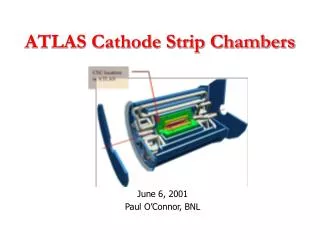
ATLAS Cathode Strip Chambers. June 6, 2001 Paul O’Connor, BNL. CSCs are the forward precision muon system of ATLAS. IP. 32 four-layer chambers 2.0 < | h | < 2.7 |Z| ~ 7m, 1 < r < 2 m 4 gas gaps per chamber 31,000 channels. Principle of operation.

ATLAS Cathode Strip Chambers
E N D
Presentation Transcript
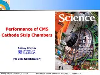
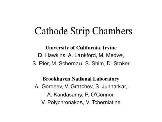
ATLAS Cathode Strip Chambers June 6, 2001 Paul O’Connor, BNL
CSCs are the forward precision muon system of ATLAS IP 32 four-layer chambers 2.0 < |h| < 2.7 |Z| ~ 7m, 1 < r < 2 m 4 gas gaps per chamber 31,000 channels
Principle of operation Determine muon position by interpolating the charge on 3 to 5 adjacent strips Precision (x-) strip pitch ~ 5.6 mm Measure Q1, Q2, Q3… with 150:1 SNR to get sx ~ 60 mm. Second set of y-strips measure transverse coordinate to ~ 1 cm. Position accuracy unaffected by gas gain or drift time variations. Accurate intercalibration of adjacent channels essential. S = d = 2.54 mm W = 5.6 mm
Gas Gain vs Anode-Cathode gap uniformity • Gas Gain, to first order, not important for Chamber precision (relative charge measurement) • Must be reasonably uniform for operational stability • Assume need to keep gain to +/- 30% - 150 mm gap tolerance
Flatness of two gaps in Module Zero Early Panel while still developing technique Min to Max variation ~6-7 % One of the later panels Min to Max variation ~4%
Corresponding Gas Gain Variation * Gas Gain Variation tracks well anode-cathode gap variation Agrees well with calculations Confidence for robust operation
CSC Electronics • On-chamber (BNL) • Amplifer/shaper (rad-hard custom ASIC) • Analog memory ( ‘’ ) • ADC (rad-hard COTS component) • Off-chamber (UCI) • Generate all control signals needed on chamber • Sparsify raw chamber data, build event, interface to T/DAQ • Initialization, calibration, monitoring • Interconnect and services (BNL) • ~ 1000 optical links, ~ 800 Gbits/s bandwidth overall • LV distribution, 2.6 kA @ 7V at chambers (18 kW) • HV distribution • Liquid cooling for on-chamber electronics • (gas system)
Reliability • Goal: < 0.1% data lost due to hard or soft fails • Strategy: on-detector electronics boards must be as simple and robust as possible • Minimal parts list: ~ 10 component types • All intelligence to reside off-chamber (SCA Controller in ROD) • ASM boards to have no • Configuration registers • Programmable logic • FIFOs • RAM • Counters • State machines • Thorough radiation test of all components • ESD protect inputs at board and chip level • ATLAS policy on grounding and shielding • Extra attention to amplifier stability • No DCS • Minimal monitoring
On-chamber Electronics Chain • Amplification, Sampling, digitization, and Multiplexing into optical fiber performed on detector. • 70 ns shaping • 10 bit dynamic range • 3 custom, radiation-tolerant ASICs To/from ROD
ASM-I ASM-II Electronics Location in Faraday Cage
4-layer ASM Board Chamber module ASM ASM Board Board y -strips x-strips ASM ASM Board Board bidirectional optical fiber links Readout organization – one chamber • 864 channels per chamber • Optical links: • 10 downlinks, 5 uplinks per chamber
ASICs for CSC Electronics CHIP TYPE FOUNDRY TECHNOLOGY • P/S analog Agilent AMOS14TB • SCA mixed ATMEL DMILL • MUX digital TBD TBD • POS. VREG power ST RHBip1
Preamp/Shaper (P/S) • Technology: Agilent 0.5 um CMOS • Function: 12-channel preamplifier and 7-pole shaper • No. of chips required: 5,120 (full scope of 64 chambers) • MPW runs: 3 • Tested with full size chambers in beam • Radiation testing: preliminary ionizing test to 1 Mrad, very encouraging result • Milestones: • Beam test 09/01 • Final DR and PRR 10/01 • Production 12/01
SCA • Technology: DMILL • Function: analog memory • Design responsibility: LARG • No. chips required: 5,120 for full scope (64 chambers) • This is the same chip used in LARG FEB • Design was modified at our request to allow pin-selectable “MUON mode” • Effectively increases the readout rate by X6 • 4 channels x 3 gains => 12 channels • Duty cycle 50% => 100% per SCA • Read clock 5 MHz => 6.67 MHz • Tested in MUON mode in lab, 3/01- 5/01 • LARG in control of radiation qualification, procurement, and production testing • Production forseen for Jan. 02
MUX • Function: data concentration between ADC and G-link • Technology: TBD • No. of chips required: TBD • Milestones: • Start design 10/01 • MPW fab 02/02 • Final DR 10/02? Voltage Regulator • LHC4913 positive voltage regulator being developed in framework of RD-49 by ST Microelectronics Catania • Location: ASM-1 and ASM-2 • Quantities required: 640 ea. 5V and 3.3V (for 32 chambers)
Noise vs. capacitance Linearity Simulated:Measured:o
Preamp/shaper 60Co irradiation results Supply current Gain Noise Waveform
ASM-2a Noise Measurement IC50 preamp/shaper (unpulsed) into SCA on ASM-IIa board Channel 1 results displayed 24 SCA cells written and read out Measurement repeated for 1000 cycles. Histogram of all cells Mean and s.d. of each cell
CSC Off-detector electronics optional
ROD • Functions: • Generate control signals and transmit to chambers • Receive and process raw chamber data • Assemble events and transmit to Concentrator • Calibration and monitoring • ROD serves 2 chambers (1920 channels, 12.8 Gbit/s) • 9U VME plus 220 mm Transition Module, 100W • Modular design using TI DSP-based daughterboard (GPU) • 70 x 70 mm, 3W • > 100 Mword/s data BW • Component cost ~ $300 • 12 GPUs per ROD • Status: • GPU: working prototype on hand • ROD: motherboard layout started 5/1/01 • Milestones: • Prelim. Design Review 05/01 • First prototype in hand 08/01 • Integration with ASM-2 04/02 • Final design review 10/02 • PRR 07/03
Low Voltage Power and Cabling • Design for full scope (64 chambers) • Uncertainties: • Power supply location • Cable run details • Local regulator characteristics • Working assumptions: • Space for LV supplies available on UX15 floor/gallery • Use LARG-like supplies if neutron flux too high for standard DC-DC converters • 25m run to patch panel on outside of endcap wheel • 12 m from edge of endcap to chamber pigtail • Total electronics power: 18400 W (2630A @ 7V) • Cabling: 64 pairs AWG 4, 480 cm2, 1000 kg • 100 W dissipated per cable, 6400 W total for full scope • Fiber optic cables • 960 fibers from USA15 (120m run) • 90 cm2 cross section, 860 kg
Prototype Recirculating Gas System Design and Construction by L.Kotchenda (PNPI) and his crew at BNL System design similar to final Will be used in test beams Important for long term aging tests foreseen using X5/GIF
High Rate Performance • Overall background rate 107 Hz per chamber • 50% charged particles, 50% neutron and g • Charged particle background is rejected by • Timing window around trigger (out of time) • Or by pattern recognition of non-projective tracks • Neutrals can deposit high charges • 50% of neutrals above QFS • 1% of neutrals above 6* QFS • Neutrals produce short-range electrons usually confined to 1-layer • But a neutral hit anywhere in chamber induces crosstalk onto all strips by anode-cathode crosstalk:
Summary • Chambers ready for start of production • Two of 4 ASICs ready for production • MUX and Voltage Regulator ASIC must be resolved as quickly as possible • Location of power supplies must be resolved • System test with Module 0 chamber, ASM boards this Fall • System test of optical links and ROD next Spring
BNL: V. Polychronakos P. O’Connor A. Kandasamy S. Junnarkar A. Gorodeev V. Tcherniatine V. Gratchev UCI: A. Lankford D. Stoker M. Schernau S. Pier D. Hawkins N. Drego J. Dailing B. Toledano The CSC Team