Download
1 / 24
280 likes | 888 Vues
Key Concepts RC and RL circuit equations First-Order circuit step response Initial and Final Conditions Zero input response First-Order circuit response to exponential and sinusoidal inputs Natural response Forced response. DC steady-state response Zero-input response Zero-state response

E N D
Key Concepts RC and RL circuit equations First-Order circuit step response Initial and Final Conditions Zero input response First-Order circuit response to exponential and sinusoidal inputs Natural response Forced response
DC steady-state response • Zero-input response • Zero-state response • Initial conditions • Final conditions • Second-order circuits • Damping • Under damped • Critically damped • Over damped • Undamped natural frequency • Natural frequency • Standard form Keywords First order circuits Characteristic equation Time domain Transient Natural response Forced response Sinusoidal steady state response AC steady-state response Zero-frequency
Reading The Analysis & Design of Linear Circuits Sections 7-1 to 7-6 Pages 313-337 Roland E. Thomas, Albert J. Rosa Gregory J. Toussaint
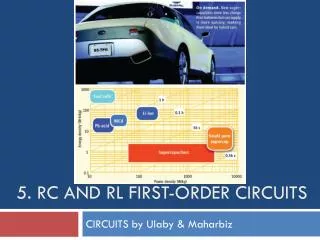
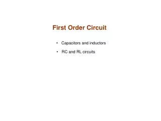
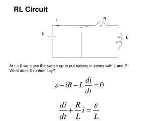
First-Order Circuits • A circuit which contains only sources, resistors and an inductor is called an RL circuit. • A circuit which contains only sources, resistors and a capacitor is called an RC circuit. • RL and RC circuits are called first-order circuits because their voltages and currents are described by first-order differential equations. R R i i vs – + vs – + C L
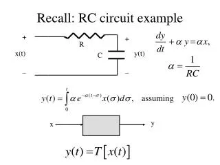
RC and RL Circuit Equations RC Circuits – Natural Response Any linear circuit can be replaced by its Thévenin equivalent Generalizes any first-order circuit… …to a voltage source, VT(t) in series with a resistor RT Examine a simple circuit
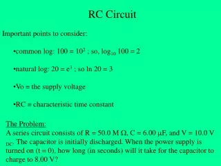
RC and RL Circuit Equations RC Circuits – Natural Response What is the characteristic equation? Finding the characteristic equation Solving the characteristic equation
RC and RL Circuit Equations RC Circuits – Natural Response Solving for the natural response Writing a KVL equation Substitute for i(t)=CdvC(t)/dt The solution should be of the form vC(t)=K est… First-order linear differential equation with constant coefficients
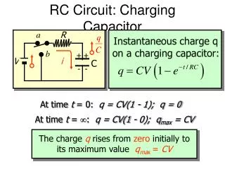
RC and RL Circuit Equations RCCircuits – Natural Response Solving for the natural response The solution… Substituting Solving for s vC(t) = K e(–t/RC) Then for K at t = 0
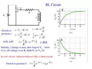
RC and RL Circuit Equations RL Circuits – Natural Response The solution to first order RL circuits follows naturally We use the Norton equivalent circuit and KCL The results will be the dual of the series RC circuit. (V↔I, C↔L, R↔G)
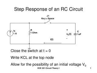
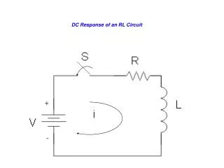
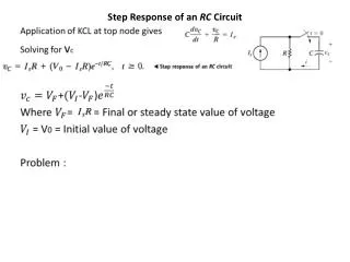
RC and RL Circuit Equations RC Circuits – Step Response Examine how and RC circuit responds to a step input The circuit now has an input v(t) What do we know The input sources, VT(t) The various parameters RT and either C or L The value of the initial condition for VC(t) or IL(t) at t=0 Start with the first order differential equation for the RC circuit
RC and RL Circuit Equations RC Circuits – Step Response Start with the first order differential equation for the RC circuit The solution will be composed of two parts The natural solution The forced solution Use superposition to find each then combine vC(t) = vCN(t) + vCF(t)
RC and RL Circuit Equations RC Circuits – Step Response The natural response vC(t) = K e(–t/RC)
RC and RL Circuit Equations RC Circuits – Step Response The forced response From the original equation The step is considered a DC input Assume a solution of the form KA
RC and RL Circuit Equations RC Circuits – Step Response The forced response The final response
RC and RL Circuit Equations RC Circuits – Exponential Response Follow the same process as for step input Assume the natural response is of the form The natural solution is VA e-αt
RC and RL Circuit Equations RC Circuits – Exponential Response The forced response, VF(t), depends upon The Circuit The nature of the forcing function Assume a solution of the form KA e-αt
RC and RL Circuit Equations RC Circuits – Exponential Response Solve for KF
RC and RL Circuit Equations RC Circuits – Exponential Response Combining the two solutions We solve for K using the initial condition v(0) = V0
RC and RL Circuit Equations RC Circuits – Sinusoidal Response Now examine the response to a sinusoid We follow the same process The natural response will be the same Assume a forced response of the form VF(t) =Kacost + Kbsint
RC and RL Circuit Equations RC Circuits – Sinusoidal Response Substituting for VF (t) gives Comparing coefficients gives
RC and RL Circuit Equations RC Circuits – Sinusoidal Response Combining the natural and forced responses gives
Summary In this unit, we worked with first order circuits then analyzed how those circuits responded to basic signal inputs. Such analysis involved understanding and working with initial and final conditions when deriving the natural and forced responses.
REMINDERS: Assignments from Unit 4 are due at start of next unit. Prepare for the next unit by reading: Thomas, Rosa, and Toussaint, Sections 8-1 to 8-4, and 9-1 to 9-4 prior to coming to class. QUIZ NEXT WEEK