SNAP Calibration Hardware
200 likes | 409 Vues
SNAP Calibration Hardware. Contributors: Chuck Bower Nick Mostek Stuart Mufson Mike Sholl. *. *. *. *. SNAP Focal Plane Photometric Calibration (2% color, 1.5% individual band). SNAP throughput (transmission vs l ). Fundamental Spectrophotometric

SNAP Calibration Hardware
E N D
Presentation Transcript
SNAP Calibration Hardware Contributors: Chuck Bower Nick Mostek Stuart Mufson Mike Sholl
* * * * SNAP Focal Plane Photometric Calibration(2% color, 1.5% individual band) SNAP throughput (transmission vs l) Fundamental Spectrophotometric Calibrators (white dwarfs, G2 stars) STARCal? pre-launch measurements space-based measurements Fundamental Spectrophotometric Calibrators calibrate subpixel regions Primary Field Calibrators on same subpixel regions Ring of Fire Low Frequency Spatial Flats – star fields High Frequency Spatial Flats – LEDs, RoF Transfers calibration from subpixel regions Focal Plane calibrated for photometry Spectrograph monitors LED spectral shape Bare photodiodes monitor RoF irradiance
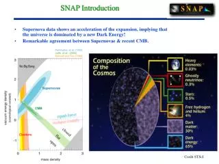
SNAP Calibration Requirements • The cosmological parameters measured by SNAP will be limited by the systematic errors of SNIa photometric measurements • The SNAP calibration group has been working towards an error requirement of 1.5% in-band (2% color) photometric calibration • IU has the responsibility for designing and testing the SNAP onboard photometric calibration system • IU is also taking a lead role in the design and calibration of SNAP broadband filters Ring of Fire
Monochromator Calibration Light System Overview • Ring of Fire (RoF) illuminates the SNAP focal plane • LED illuminator is placed away from the focal plane and operated warm • Fiber bundle connectors are included to help with system integration • Monochromator could still be incorporated in the light system (LEDs retained for pulsing capability and stray light reduction) Light from Telescope RoF Fiber Bundle Connector Radiation Shield Silica Fiber Bundle Filters LED Illuminator Focal Plane Photodiode
Ring of Fire Design • Design and engineering done by Mike Sholl at LBNL • Fiber bundle illuminates an annular mirror and projects an elliptical spot on a diffuse Spectralon surface • Initial design uses 7 fiber bundle ports to achieve uniform illumination • 300 micron core diameter fiber with wavelength coverage from 400nm-1700nm • IU involved in designing and testing optical fiber bundle
LED Illuminator Testing Focal Plane Uniformity from RoF Fiber Port Variation = 10% Spectralon Thermal Stage 2.7% variations Fiber Bundle azimuth • Illuminator must support thermally controlled, redundant LEDs and uniformly illuminate a fiber bundle • Fiber port variation causes azimuthal non-uniformity on the focal plane • LED illuminator mock up will test the efficiency and uniformity of the conceptual design • Initial calculations show that 30k e- signal can be achieved in 300s integration • 4inch diameter hemisphere should hold at least ~150 LEDs (depending on how they are packed)
Ongoing LED Testing • IU continues to catalog a wide range of LEDs with undergraduate help • Multiple LEDs of the same type have also been cataloged • Total LED output changes by 1% per 1°C • Testing will include radiation testing at the IUCF this fall
Monochromatic Illumination & Cryogenic Calibration System • System to help determine tolerances on SNAP calibration hardware • Designed to be a versatile, fully automated illumination and measurement system • Immediate Goals: • Transfers the irradiance calibration from a NIST photodiode to a photodiode operated at SNAP temperature (PITS) • Calibrated photodiodes will be used in QE measurement systems at Michigan, CalTech, and LBNL • Test interference filters transmission at SNAP temperature with an f/10 beam at a SNAP range of angles • Most parts are in hand and assembly is now in progress Front Monochromator Photomax Dewar NIST Photodiode Imaging lens & baffle Integrating Sphere Back Monochromator Blocking Filter Wheel Linear Stage 6
NIST TE-cooled InGaAs photodiode Transfer candidate no TE cooler NIST Calibrated InGaAs Irradiance Standard • NIST photodiode has a precision-bored, black anodized aperture with near-knife edge thickness • 1s error is 1.5% at 0.7mm and 2% at 1.7mm, a large improvement over previous 5% calibration • Effective aperture area measured independently by NIST, contributes largest portion of error in irradiance (1%) • Photodiode uniformity was calibrated from NIST cryogenic radiometer beam which was raster scanned over the diode surface
PITS Setup Electronics Connector Dewar Mounting Bracket Dewar Mounting Rails
NIST Diode Bracket Cold stage Transfer Diode Housing Insulating Halon Linear Stage PITS Setup
Photon Count Incidence angle Cold Interference Filter Testing • What tolerances are required to maintain calibration of filter throughput? • Interference filter throughput will change from room temperature to SNAP focal plane temperature • Interference filter throughput is also affected by the incident angle of light. Most filters are referenced and tested at normal incidence, but SNAP photon incidence is significantly off-normal • SNAP filters require a cryogenic testing facility that mimics the SNAP observing conditions
Cold Interference Filter Testing Dewar Monochromatic light • Laboratory setup to simulate filter conditions onboard SNAP • Filter will be held at SNAP focal plane temperature • SNAP secondary and spider shadow can be modeled and attached to the exit port of an integrating sphere • NIST diode will be placed a working distance from the sphere port to simulate the 5° solid angle of incident light expected on the SNAP focal plane (apodization) • Filter rotation stage will place filter at an incident angle of 10°, 15°, and 20° (SNAP off-axis incidence angle) Integrating sphere SNAP secondary shadow Cold filter Rotation stage NIST photodiode
LED Thermal Controller Mirror Grating QTH Lamp LED Filter Tracking Method Monochromator Procedure • Measure filter transmission with QTH lamp at normal incidence and 10 filter angle • Measure LED spectra w/o filter and then with normal and 10 filter angle • Measure entire LED emission (mirror replaces grating) at normal and 10 filter angle Filter on Rotating Stage Integrating Sphere Focusing Optics Photodiode 3-D Stage IntegratingCircuit
Filter Transmission with LEDs and a Monochromator • Overlapping LED transmissions combined and weighted by S/N of monochromator measurement LED 1 LED 2 LED 3 • LEDs work as well as a QTH lamp source when combined with a monochromator
Broadband LED Measurements • Can LEDs be used without a monochromator? • Simplifies calibration system design • Increases number of photons to the focal plane • Must compare “Broadband” LED Signals • For each LED and filter incident angle, integrate to get the total spectral power • Compare transmission of integrated LED spectral power to measured transmission from broadband LED power • Back out filter transmission change using initial LED / Filter throughput and the change in the LED broadband measurements LED 1 LED 2 LED 3
Prescription for using Broadband LEDs t(leff) t(l’eff) ’ eff ’eff • Create spline functions from LED spectral power P(l) and original filter transmission t(l) • Expected broadband transmissions for i=3 LEDs come from • Perturbed broadband transmissions used in c2 where t΄is allowed to vary through three parameters of leff , Dl,and A=t(leff)*Dl where mLED is the measured broadband LED transmission • Minimize c2 to get parameters for final t΄(l)
Monochromatic Light vs Broadband LED • Points = Monochromatic transmission measurements • Lines= Transmission fits from Broadband LED measurements • LED Fit Method differs from monochromatic measurements by at most 3% • Input this transmission error into a SNAP simulation to get requirements on calibration method
Effect of Filter Calibration on Cosmology • Using the SNAP simulation framework to test filter calibration • Introduce a filter set based on the shape of our measured filter • Compare cosmologies between a perfectly known filter set and a filter set with imperfect calibration (such as our measured filter throughput via broadband LEDs) • Work in progress as SNAP simulation software is being debugged
Summary • IU has a principal role in the design and testing of SNAP calibration hardware • Ring of Fire design is progressing. Now includes fiber interface and LED illuminator concept • LED Illuminator testing continues in earnest • Monochromatic Illumination and Cryogenic Calibration System being built at IU • PITS characterization to begin this fall, cold filter transmission testing will follow thereafter • Filter tracking can be done with monochromatic light or characterized LED light when coupled with a monitoring photodiode • Using laboratory filter tracking measurements, a simulation of science-driven calibration requirements is in progress