Download
1 / 1
10 likes | 286 Vues
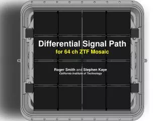
Fully differential signal path for the ZTF mosaic Roger Smith and Stephen Kaye California Institute of Technology.

E N D
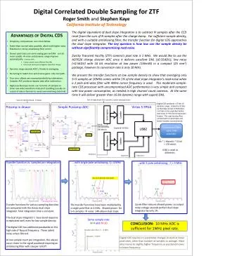
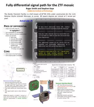
Fully differential signal path for the ZTF mosaic Roger Smith and Stephen Kaye California Institute of Technology The Zwicky Transient Facility is a 4x4 mosaic of 6K*6K CCDs under construction for the 1.2m Palomar Oschin Schmidt Telescope, to survey 80 square degrees per minute at 1 arcsec per pixel. Actual size • Pros of differential • Video cross talk reduced • negligible ? • Less susceptible to interference. • These become common mode errors which are rejected: • Bias noise • Ground differentials • Reset feedthrough • Clock feedthrough • Clamp control signal feedthrough. • AC coupler drift • clamp once per line. • Cons • CCD noise is incurred twice. • CCD output power is doubled. To keep beam obstruction below 23%, readout electronics must be mounted outside the telescope. Sixty four video channels must be transmitted over >1 m of cable at 1 MHz to meet the 10 second read time requirement. True differential outputs of e2v 231-C6 CCD are amplified and transmitted differentially to a differential input ADC performing digital CDS. The goal is to get close to 7e- = √2 * “typical noise” quoted for single channel operation and to eliminate the need for crosstalk correction. Extra-focal imager Guider Extra-focal imager Extra-focal imager • AD8066: • Output swing to 50mV of rail for I0 = 30 mA • GBW = 146MHz • en = 7 nV/√Hz • IB = ±1 pA • PD = 66mW per op amp • Conductively cooled via ground and supply planes • ADG601: • IL = ± 10 pA • Ron = 2.5 ohm Signal chain increases total noise by ~ 4%. Adiff = (R0+R1+R2)/R0 ACM = 1 when R1=R2 Input referred • Black level clamping at AC coupler: • Active during vertical transfer only • Can close reference side switch to convert to single sided CCD output (lower noise) while preserving differential transmission. • Close both switches for shorted input noise test. • Close signal switch only to check reference side. • Differential preamp is located in vacuum at warm end of CCD flex cable. Drives balanced strip-line implemented in vacuum interface board • COTS cables: • Samtec ERDP-049 twinax 32 pair • Glenair177-710 shielded 100 pin • Vacuum Interface Board • 1/8” thick PCB carries preamps • Trapped between two O-rings in side wall and back cover. • Signals routed on internal layers. • Outer layers are isolated, in contact with case: conduct heat from preamps. • Eliminates hermetic connectors. • COTS cables connect directly to edges: all custom wiring in PCB. A-A A A Earlier version 2013 Scientific Detector Workshop, Florence