Download

1 / 9
90 likes | 204 Vues
This detailed diagram illustrates the advanced interconnection layout for a 6m high telescope with a 48" aperture. The design includes connectors, electronic racks, detectors, and cables for efficient operation.

E N D
ZTF Interconnecting Scheme Stephen Kaye 2013-4-22
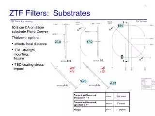
Telescope Diagram • Telescope 6 m high with 48” (1.22 m) aperture • Slight angle (3º) of telescope body • Detector mounted at 3 m location in middle of aperture • Spider mounts detector to telescope • Hatch near spider for routed cables • Mount electronics rack near hatch Detector Spider Hatch Electronics Rack Telescope Body
Connectors • Pin outs are listed in Excel Spreadsheet • Three connectors for 2 CCDs • 2 Micro D Connectors • 1 ERF8 Connector • Connectors split by function • 1 Bias connector • 1 Clock Connector • 1 Video Connector
Slot layout Digital Card slot width TBD: • If 1” per card, two rows required. • If 0.8” per card it all fits in one row. • May need 1” for trace routing down to cable connectors. • Is there room for plug in supply module or does this go in base (or top of enclosure 6U card slot power analog 1U extension, can increase to 2U Video Clock Bias Cables exit out of page, then turn. Cooling infrastructure behind connectors, maybe power supply too.
Controller Rack Max = 21 slots *0.8” = 16.8” • Mount 8 sets of cards in chassis • Chassis is 19” rack mountable • Customized backplane fitted to off the shelf VME crate
VIB Board • Same connectors will be mounted to VIB board • Off the shelf cables can be used for harnessing • Connectors at edge are outside the dewar vacuum
Card features • Front panels for full shielding. • No connections to CCD from front panel; maybe some test points (eg BNC) or indicators. • LED/indicator power toggled on/off by momentary switch. Turns on at power up. Turns off whenever software initialized. • All cards have ejectors and locking screws. • All cards can work on card extender.
Backplane connector features • Multiple pin lengths (eg see 2mm hard metric or “metral” connectors used in Compact PCI.) support: • ESD to ground and supply instead of signal (CCD) pins. • Accidental hot swap not catastrophic. • Prefer connectors along long dimension (height) of card so fewer columns of pins (often called rows) are needed: easier to route traces. • Shielded connectors available (probably not needed). • Wrap tail pins on backplane serve as test points or jumper locations. • Can be cut short for speed critical pins. • Can be covered with insulative sleeve for CCD outputs that are vulnerable to shorts though we have none since we have preamp in dewar.
Other features for electronics box • Closed to external air/dust; minimizes hot air leakage. • Heat exchanger, liquid cooled? • Forced air recirculation or conductive via shield plates between slot? • Decision is yet to be made on supply packaging, either: • Modular, plug into backplane (easy to replace) • Flat supply module directly mounted to heat sink (easy to cool) • Power supplies: • Standard voltages: 3.3V, 5V, 12V, 15V • Current consumption TBD, ….please advise. • Power connector, switch, indicator and fuse on front panel