ZTF Optics Design
ZTF Optics Design. <P. Jelinsky > 2013-02-01. Optics Outline. Overview of Requirements Trade Studies Conceptual Design Future Work. Requirements Overview. Use the Oschin Schmidt telescope primary and corrector


ZTF Optics Design
E N D
Presentation Transcript
ZTF Technical Meeting ZTF Optics Design <P. Jelinsky> 2013-02-01
Optics Outline ZTF Technical Meeting • Overview of Requirements • Trade Studies • Conceptual Design • Future Work
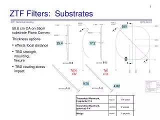
Requirements Overview ZTF Technical Meeting • Use the Oschin Schmidt telescope primary and corrector • Illuminate 12 CCD231-C6 e2v detectors (6k x 6k, 15 µm pixels (~ 1 arcsecond)) • 16 detectors had large vignetting and worse imaging (see next slide) • R band average FWHM < 1.1 arcseconds (final, including alignment and manufacturing) • Allow 1.0 arcseconds for the optical design • G band average FWHM < 1.2 arcseconds (final, including alignment and manufacturing) • Allow 1.1 arcseconds for the optical design • Use materials that transmit in the U and I band • May add these filters later
Requirements Overview (continued) ZTF Technical Meeting Detector Pattern (with vignetting) No Vignetting 10%Vignetting 20%Vignetting 30%Vignetting
Initial Trade Study Inputs ZTF Technical Meeting • Distance from flattener to CCD is >= 2mm • Allow distance from Schmidt corrector to mirror to vary • Window diameter/thickness <= 14.4 (same as QUEST camera) • Safe to have atmospheric pressure accross • Window is Fused Silica • All spherical surfaces • Aspheric surfaces did not change performance much • Optimize over 5 wavelengths in the g’, r’ bands as below (allowing a focus change). • Optimize over 9 field points • Merit function is the 2D FWHM (RMS radius * 2.3548)
Bandpass Definition ZTF Technical Meeting
Initial Trade Study ZTF Technical Meeting • Initially did not include a filter in the trade study and concentrated only on the R band • Filter seemed to always make design worse • Quicker to analyze to limit trade space
Initial Trade Study ZTF Technical Meeting • No designs with flat detectors and vacuum windows met requirements
12 Segment Focal Plane Schematic ZTF Technical Meeting Filter Window 12 flatteners 12 detectors
12 Segment Focal Plane Schematic ZTF Technical Meeting • Each detector is flat but tilted with respect to the others (see previous slide) • 12 chords on focal plane • One vacuum window for all detectors (see previous slide) • After FEA center thickness fixed at ~22mm • Each detector has its own field flattener (see previous slide) • Allow field flattener to be decentered and tilted
12 Segment Focal Plane Inputs ZTF Technical Meeting • Distance from flattener to detector > 2mm (smaller preferred) • Distance from flattener to window from 3 mm to 110 mm (larger preferred) • Distance from window to filter from 15 mm to 110 mm (larger preferred) • Filter, Window, and flatteners are Fused Silica • Good transmission in UV and IR • Only Optimized G and R band simultaneously (allowing focus change) • Optimize over 5 wavelengths in the g’, r’ bands • Optimize over 9 field points in each detector • Merit function is the average 2D FWHM (RMS radius * 2.3548) • Use RMS field map with 50 x 50 points
12 Segment Focal Plane Trends ZTF Technical Meeting • Thicker Windows degrade optical performance • 22mm center window thickness gives factor of safety of 8 (from FEA analysis) • Thicker filter degrades optical performance • Flat filter degrades optical performance • Larger CCD – flattener spacing degrades optical performance
12 Segment Trade Study ZTF Technical Meeting • PTF Corrector Distance = 6075.3 mm; Original Corrector Distance = 6122.4 mm • (A) = asphere • (S) = sphere
Case XV Imaging Results (1 Quadrant) ZTF Technical Meeting R Band G Band • R Band average FWHM = 0.60 arcseconds; maximum FWHM = 0.88 arcseconds • G Band average FWHM = 1.00 arcseconds; maximum FWHM = 1.26 arcseconds FWHM (arcseconds)
Future Work ZTF Technical Meeting • Finish I and U band results • Complete optical tolerance analysis • Budget/split tolerances into telescope and cryostat sections • E.g. filter location (part is telescope filter mechanism/ part is cryostat manufacture) • Complete vignetting/obscuration analysis • Complete ghosting/scattered light analysis • Complete manufacturability/cost studies
ZTF Technical Meeting Backup slides
Detector Gap ZTF Technical Meeting • If t is the thickness of the flattener, d is the distance from detector to the flattener, c is the chamfer of the flattener, g is the gap between the flatteners, f is the f/# of the beam, n is the index of refraction of the glass, and s is the spacing between the detectors, then • For g = 2mm, c = 1mm, t = 5mm, d=2mm, f=2.5, n = 1.5 then s = 8.2 mm • I assumed 8.4 mm in the analysis Field Flattener Detector
Detector Layout ZTF Technical Meeting • Two Detectors layouts have been considered • Minimize the gap in each direction (asymmetrical, need 3 detectors in Zemax) • Place detectors centers on a square grid (symmetrical, need 2 detectors in Zemax) Field locations for minimum gap Field locations for square grid • Only the minimize gap has been studied at the moment • The square grid version will be a slight modification to the optics
Minimize the gap (Zemax settings) ZTF Technical Meeting • RMS field map settings • Ray density = 6 • Data = Spot Radius • Wavelength = All • Method = Gauss Quad • Center field = 5 • Refer To = Centroid • X field size = 0.8655 • Y field size = 0.8655 • X field sampling = 50 • Y field sampling = 50 • Surface = Image • Use the text->Window->Copy clipboard to place the data into excel for analysis
Case XV Optical Prescription (Detector 1) ZTF Technical Meeting
Case XV Optical Prescription (Detector 2) ZTF Technical Meeting
Case XV Optical Prescription (Detector 3) ZTF Technical Meeting