Lateral X-rays with ESS
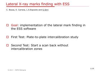
Lateral X-rays with ESS. Goal : implementation of the lateral mark finding in the ESS software test version available here: http://www.bo.infn.it/opera/scanning/lateralmarks/ Under development : integration with FlexMap3.dll and IdentityMap.dll. Lateral X-ray mark. X. Mark recognition.


Lateral X-rays with ESS
E N D
Presentation Transcript
Lateral X-rays with ESS • Goal: implementation of the lateral mark finding in the ESS software • test version available here: http://www.bo.infn.it/opera/scanning/lateralmarks/ • Under development : integration with FlexMap3.dll and IdentityMap.dll
Mark recognition Not possible to be done: • No extra camera with low magnification optics are available • Only a small amount of the lines can be scanned • The two lines are not always long enough to print a clear crossing point • Not possible to scan only one FOV per mark The approach is: • Three pieces of each line are scanned and lines are obtained by a linear fit. The coordinates of intersection point are the mark coordinates. NO NO Intersectionpoint
Getting started (for the current recommended revision)- use good mechanical references (alignment between references and motion axes better than 0.5 mm over 10 cm)- put the emulsion (and the mechanical references) with the lateral marks outside the vacuum channel as shown below.
Map String • load the map string exactly as spot-like optical marks [a MARK is the POINT given by the intersection between two X-Ray lines], example:mapext: 1005914 1 0 0; 2 771990 -3496515 897090 -3396715; 1 893967 -3494040 893967 -3494040 1 1 1; 2 893619 -3399324 893619 -3399324 1 1 1It is suggested to use real plate sizes for the brick as measured with Manual Check (if you want to use the nominal plate size, it can fail to find the first mark [at present] ). [ I'm not anymore sure about this point, I feel that the development is going to solve it. Tests are needed]. - as xy reference it is possible to use the up-left corner (max X , min Y). Open the Default Machine of the FlexStage module and ADD a XY Reference named "XYReferenceLeftUp" . • future working map string is:mapX: 0 0 0 0; 2 0 0 124946 99299; 1 121776 3529 121776 3529 1 1 ;2 121675 98172 121675 98172 1 1
Other … • Log Files:This revision produces (many) log files: c:\acq\flexmap_findmarks.log <-- the logger of the current mark finding routine c:\acq\flexmap_summary.log <-- mark stage position *append file* • Manual Set:If the system is not able to find the mark you can SET the mark manually: the mark is set as not searched and the system will try to scan again the mark using your position as starting point. You can also flag the mark as FOUND without rescanning by clicking on "set found" after the manual set. • Scanning Infrastructure (sysal2.1):The DB and the infrastructure are not yet updated to use several mark patterns for the same plate.Hence, load the 2 marks exactly as the spot case. To disable the intercalibration during scan back, put the intercalibrationID equal to the predictionID.
Strip finding strategy test revision >= 42 THREE STRIP SEGMENT ARE SEARCHED:[1] the first segment position is searched between the NOMINAL edge and the NOMINAL mark position along a LINE trajectory[2] if [1] is found, the next candidate is searched at +1mm from the [1] in one of field of view[3] if [1] is found, the next candidate is searched at -1 mm from the [1] in one of field of viewAt least 2 segments are needed. The search path of [1] is from min X,Y to max X,Y To be modified: from the edge to center and stop when the strip is found
Manual Set • If Mark Position is MANUALLY SET the strategy is to search all segments in ONE Field of View
The clone problem • The "clone" problem:The presence of a duplicated x-strip 1 mm far from the reference one ("clone") caused some failures during tests. See the mark position in the picture. This revision do not perfom any check. A recovery routine is under test in the development revision.If you suppose to have acquired the wrong one, look at log files to verify the mark positions [They should be within a few 100 microns for one brick set even if the emulsion plate is different. If a mark is 1 mm far along X is the wrong one].