
Modulation and switching
E N D
Presentation Transcript
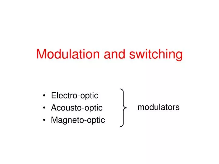
Modulation and switching • Electro-optic • Acousto-optic • Magneto-optic modulators
Electro-optic modulators Electro-optic effect – the change in the refractive index resulting from the application of dc (or low frequency) electric field The application of electric field causes redistribution of bound charge and possibly small deformation of crystal lattice. Result: the change of optical properties.
Electro-optic (eo) effect Impermeability tensor: • eo effect (charge redistribution) will depend on ratio of the applied electric field to the intraatomic electric field • the atomic electric field is typically of the order of 1010 V/m • typical values of r lie in the range 10-12 to 10-10 m/V • typical values of s lie in the 10-18 to 10-14 m2/V2 in crystals and 10-22 to 10-19 m2/V2 in liquids Pockels effect (linear eo effect) Kerr effect(quadratic eo effect) - usually observed only in media that does not exhibit Pockels effect
Permutation symmetries Impermeability tensor: symmetric tensor (like permittivity) the order is arbitrary • – 6 x 3 independent elements • – 6 x 6 independent elements (i,j) → I defined Further reduction of independent elements follows from symmetry considerations. Example: in centrosymmetric crystals
Short excurse: symmetries in crystals Symmetry operation: any operation which leaves the crystal in a state indistinguishable from the initial state. Point operation: at least one point of the crystal is fixed (e.g. rotation, reflection) 32 crystallographic point groups = point groups consistent with translational symmetry (which defines crystal)
Neumann's principle If a crystal is invariant with respect to certain symmetry operation, any of its physical properties must also be invariant with respect to the same symmetry operation. Important example: Linear eo effect in centrosymmetric crystals Centrosymmetric crystals = 11 systems in which the inversion operation i is a symmetry operation Consider applied electric field in arbitrary direction reverse the field however, the two directions are physically equivalent thus which is possible only for So no linear eo effect can exist in centrosymmetric crystals
Determination of refractive index The index ellipsoid in absence of the applied electric field The same equation in the principal axes A plane perpendicular to k passing the center of the ellipsoid. Its intersection with the ellipsoid is an ellipse whose major and minor axes have half-lengths equal to na, nb. The coordinates x,y,z are the principal axes and n1, n2, n3 are the principal refractive indices. The refractive indices of normal modes traveling in the direction k are na, nb.
Determination of refractive index The applied electric filed modifies the index ellipsoid The same equation in the principal axes (of original ellipsoid) - then we determine the principal axes and the principal refractive indices of the modified ellipsoid - finally, given the direction of light propagation, we find the normal modes and their refractive indices
Example: cubic 43m crystals (GaAs, InAs, CdTe) - isotropic crystaln1 = n2 = n3 =n - the applied field points in z direction
Example: cubic 43m crystals (GaAs, InAs, CdTe) the new principal refractive indices are:
Planar waveguide eo modulator L x V z y Ga(1-b)AlbAs n2 b<a <100> n3 Ga(1-a)AlaAs Phase modulation correction – overlap integral E.g.: V ~ 1.2 V produces phase change ~ 1 rad
Planar waveguide eo modulator L x V z y Ga(1-b)AlbAs n2 b<a <100> n3 Ga(1-a)AlaAs Polarization modulation Phase difference between TE and TM
Polarization modulation Phase difference between TE and TM
Planar waveguide eo modulator L x V z y Ga(1-b)AlbAs n2 b<a <100> n3 Ga(1-a)AlaAs Intensity modulation • n2 - n3 is at the cutoff • without the electric field the waveguide does not guide any mode • the application of the electric field increases n2 - n3and the waveguide guides the lowest mode
Planar waveguide eo modulator (different setup) Phase difference between TE and TM
High voltage sensor Ti (diffusion)
Eo modulator utilizing SPP L = 2 mm Ag layers n = 0.14 – i11 thickness 0.07 μm λ = 1.55 μm 1.1 μm eo polymer n = 1.58 – 1.59 1.3 μm buffer layer SiOaNbn = 1.56 0.934 μm waveguide SiOcNdn = 1.7 substrate SiO2n = 1.449 x z y (proposal & calculation J. Čtyroký)
Tunable frequency filter Asymmetric coupler
Bragg-effect modulator provided
Liquid crystals nematická f. – orientační uspořádání, středy molekul jsou rozmístěny náhodně • kapaliny, ve kterých existuje určité uspořádání molekul • molekuly mají doutníkový nebo diskový tvar • důsledkem je silná anizotropie mechanických, elektrických, magnetických i optických vlastností • existují tři fáze tekutých krystalů: smektická f. – orientační i jednorozměrné translační uspořádání nejvíce se blíží struktuře pevné látky • nematická a smektická f. má jednoosou symetrii • optická osa je rovnoběžná s osou molekul permitivita (statická) cholesterická f. – orientace vykazuje šroubovicové stočení optická osa
Jednoosé kapalné krystaly Po přiložení statického nebo nízkofrekvenčního elektrického pole E se optická osa orientuje ve směru E, pokud optická osa orientuje ve směru kolmém na E, pokud tak, aby byla minimální volná elektrostatická energie (kladný jednoosý krystal) (záporný jednoosý krystal) složky E ve směru hlavních os odezvová doba: ms
Jednoosé kapalné krystaly Index lomu: no pro vlnu polarizovanou kolmo na optickou osu ne pro vlnu polarizovanou podél optické osy Pro vlny (řádná a mimořádná vlna) šířící se ve směru svírajícím úhel θs optickou osou jsou indexy lomu no Pro všechny známé nematické a smektické krystaly platí ne > no.
Example: Liquid crystal switch ng = ne ne > no
Akustooptické modulátory Fotoelastický jev = změna indexu lomu prostředí vyvolaná mechanickým namáháním Akustooptický jev = změna indexu lomu prostředí při průchodu zvuku
Akustooptický jev impermitivita tenzor deformace fotoelastický tenzor rovinná akustická vlna s intenzitou [W/m2] způsobí změnu indexu lomu materiálový parametr vyjadřující míru ao jevu
Bragg diffraction B B Bragg cell
Debye-Sears (Raman-Nath) scattering Order = -1
Bragg diffraction Zákon zachování energie foton ħω, ħk zanikne foton ħω’, ħk’ vznikne Zákon zachování hybnosti fonon ħΩ, ħK zanikne vznikne Obvykle: je nejvýše
Interakce optické rovinné vlny s akustickou rovinnou vlnou úzkým akustickým svazkem akustická rovinná vlna se šíří ve směru vlnového vektoru K akustický svazek se skládá z rovinných vln, které se šíří v různých směrech K vícenásobný rozptyl je zakázán vícenásobný rozptyl je povolen 3 2 1 1 0 0 -1 -2
Braggova difrakce v anizotropním prostředí Zákon zachování energie Zákon zachování hybnosti
Dále jen Braggova difrakce uspořádání s malým a velkým Braggovým úhlem L je v obou případech interakční délka Jak závisí intenzita na L?
Uspořádání s malým Braggovým úhlem x z předp.:
x malý z
Uspořádání s malým Braggovým úhlem x z předp.:
Uspořádání s velkým Braggovým úhlem (a) případ z x umíme řešit, viz. vazba mezi mody, které se šíří ve stejném směru, případ l = 1 fonon emitován/absorbován
Uspořádání s velkým Braggovým úhlem (b) případ z x umíme řešit, viz. vazba mezi stejnými mody jdoucími v ±z