Download

1 / 55
560 likes | 915 Vues
Dose Prescription (CcGE) and Patient-specific QA. Narayan Sahoo. Plan of the presentation. Proton specific dose prescription Patient-Specific QA measurements Our current practice Future plans. Physical dose (cGy) vs biological effective dose (CcGE). Protons have higher RBE.

E N D
Dose Prescription (CcGE) and Patient-specific QA Narayan Sahoo
Plan of the presentation • Proton specific dose prescription • Patient-Specific QA measurements • Our current practice • Future plans
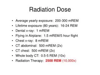
Physical dose (cGy) vs biological effective dose (CcGE) Protons have higher RBE. “Most radiobiological data agree that RBE=1.1 for proton beams compared to photon beams in typical irradiation conditions for the biological systems relevant in therapy”, from IAEA working group report, A. Wambersie et al. Radiation Protection Dosimetry (2006). Clinically 1 cGy of proton beam dose is equivalent to 1.1 cGy of Co-60 gamma rays dose or 1 Cobalt cGy Equivalent (CcGE) dose. Our practice: Calibration in cGy, plan in CcGE.
Aperture & compensator QA BEV showing aperture outline and compensator iso-thickness lines • Aperture and compensator ‘overlay’ printed on acetate at the virtual source-to-aperture distance: • (VSAD – snout position – 3 cm) x (270 / VSAD) • Good check of aperture size, shape, rotation and translation. • Qualitative visual test only of compensator design. • Plunge depths measured at X and Y coords, and compared to TPS
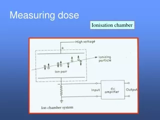
Patient specific QA- Assurance of correct dose delivery • Dose calibration protocol (IAEA-TRS398) • MU Measurement procedure • MU calculation procedure • 2-D and 3-D dose verification Starting point of MU determination process is the creation of a verification plan Patient specific beam parameters, aperture and compensator are used to generate a plan in a water equivalent phantom
Verification plan (VP) • It gives the dose for calibration in measurement phantom • It can give us some idea about the magnitude of compensator (CF) and patient scatter factors (PSF) Dose in VP without compensator *CF = Dose in VP with compensator Dose in VP with compensator * PSF = Dose in Patient PSF = CF*PSF Large CF and CPSF is an indication complex compensator and large patient inhomegeneity Raises doubt about the accuracy of the pencil beam model Requires verification
Dose Calibration • Reference Calibration Settings: 250 MeV, Range=28.5 cm. SOBP=10 cm, depth = 23.5 cm, 10 cm x 10 cm aperture, Chamber at isocenter, SCD = 270 cm, Snout at 45 cm • Dose = 1 cGy/MU • Treatment field settings differ from reference conditions - need Dose/MU measurement or calculation
MU Measurement procedure • Q: the charge in nC for 100 MU (100 cGy) under reference calibration condition • Thus, Q (nC) from 100 cGy. • 1 (nC) from 100/Q cGy • P: charge measured in nC for 50 MUs for patient treatment field • Dose for P (nC) = P*100/Q cGy for 50 MU • Dose per MU for patient treatment field = P*100/(Q*50) cGy = d (cGy/MU) • MUs for dose D cGy = D / d
MU Measurement procedure • An inverse square factor (ISF) is used to correct the MUs if the source to point distance (SSD + physical depth) is not equal to 270 cm, which is our calibration source to chamber distance. • ISF = (270 / (270+physical depth))^2
MU Calculation procedure Treatment field parameters for passively scattered proton beams leading to different D/MU from the reference D/MU are: ParameterFactor • beam energy, ROF • SOBP width, SOBPF • Thickness of range shifters RSF • Distance of the calibration point from the center of SOBP OCF
MU Calculation procedure 5. Source to calibration point distance ISF 6. Field size FSF 7. Compensator and Patient Scatter Factor CPSF Table of measured ROF, SOBPF, RSF factors are available MU=dose/(ROF.SOBPF.RSF.OCF.FSF. ISF.CPSF) FSFs are measured on case by case basis, are usually equal to 1 for aperture sizes larger that 5 cm x 5 cm CPSF is taken as the ratio of patient plan dose and dose at the water equivalent depth in verification plan without compensator at the same Source to Point Distance as in the patient plan EXCEL Work sheets are used for measurement and calculation
Current practice • Run VP without compensator and with compensator • Use VP without compensator dose to calculate MU • If compensator factor is large, find a suitable measurement point with small thickness gradient to measure the CF • Check the accuracy of Eclipse calculation taking into account the limits of the measurement • If large discrepancy, inform the physician about more than usual uncertainty in dose delivery for these complex fields
Questions about VP and measurements with compensator • Compensators are designed to modify the proton range and should, ideally, have no effect on dose • However, due to scattering they do affect the magnitude of dose slightly and complex compensators may make dose distribution quite inhomogeneous. Perturbation of dose is depth dependent • For a complex compensator, choosing a point of verification in a flat dose region away from compensator complexities does not provide information about the effect of complexities on dose distributions • Selecting a point near the complexities and in regions of high dose gradients makes measurements inaccurate • So, how does making dose measurements at one or a small number of points in the presence of a compensator help From: Radhe Mohan, Ph.D.
Dr. Mohan’s comments (continued) Eclipse makes approximations (ignores lateral scatter) in compensator design but the final dose calculation takes it into account, although still approximately. However, measurements at points in flat dose regions around the middle of an SOBP would not verify Eclipse's calculation. Dosimetric verification of a compensator calculation should ideally include measurement of range at all points across the field, but that would be resource intensive using current systems. (Perhaps dose distribution measurements with a matrix chamber at a series of depths may be an answer).
Response • We need to find a procedure to check the accuracy of Eclipse calculation of dose for complex compensators and in inhomogeneous media • We do not measure if compensator factor is small, like in prostate or whole brain • Ion chamber measurement at one suitable point gives some indication of the extent of uncertainties in dose calculation • We sometimes do 3-D dose verification by Mapcheck, film and ion chamber arrays
Comparison of calibration point doses (CcGE)- plan vs. verification plan
Mean and Standard deviation of the differences between calculated and measured MU. (May 2006 to February 2007) More dosimetry data have been collected since this statistics was done. Agreement between measurement and calculation is mostly within 1%. As of 2/18/08, MU measurements for treatment fields of about 760 patients are performed.
2-D and 3-D dose verification • Necessary for comprehensive validation of Eclipse TPS and for QA checks of complex treatment portals- e.g. patch fields, junctions • Water tank scanning of SOBP and profiles-can give 3-D information, but time consuming • Films, diode array (Map Check) and ion chamber array (Matrixx) will be practical
posterior Patient 1 Profiles - AP • Verification plan • Water phantom • 250 cm SSD • Depth = 18.8 cm • Anterior-posterior along the central axis • Pin-point chamber • Meas on 2/16/08
Feet Patient 1 Profiles - SI • Verification plan • Water phantom • 250 cm SSD • Depth = 18.8 cm • head to feet along the central axis • Pin-point chamber • Meas on 2/16/08