Download
1 / 17
210 likes | 593 Vues
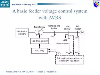
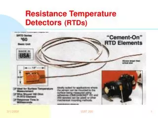
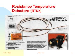
Resistance Temperature Detectors (RTDs). Bridge Circuits. ISAT 300 Spring 1999. Wheatstone Bridge. A circuit designed to measure changes in resistance In Instrumentation it is used as signal conditioning for strain gages. R 1. R 2. +. -. +. V s. V o. -. R 3. R 4. A. B. D. C.

E N D
Bridge Circuits ISAT 300 Spring 1999 ISAT 300
Wheatstone Bridge • A circuit designed to measure changes in resistance • In Instrumentation it is used as signal conditioning for strain gages ISAT 300
R1 R2 + - + Vs Vo - R3 R4 A B D C ISAT 300
V2 R2 + Vs - R3 V3 Build a Wheatstone Bridge ISAT 300
Build A Wheatstone Bridge Apply Kirchoff’s Voltage Law: V2 V1 R1 R2 + Vo Vs - Or R4 V4 R3 V3 ISAT 300
Balancing the Bridge Governing Equation Multiply by a common denominator Simplify ISAT 300
Balance The Bridge The bridge is balanced if the output is zero ISAT 300
For RTD circuits we can get RRTD as a function of Vo Start with If R3 is the RTD, then Design with R1=R4, then With some algebra, ISAT 300
RTDs: Characteristics and Applications • Characteristics: • Resistive device, active, linear • Large range: -200 to +850oC for Platinum • High accuracy: 0.001oC • Low sensitivity: 0.39 % per oC • Don’t need reference temperature • Applications: • Industries and laboratories where high accuracy of temperature measurements are required. ISAT 300
Thin-Film RTDs Thin-film RTD design is a newer technology and is gaining favor due to lower cost. It is designed to minimize strain on the platinum due to thermal expansion since strain also cause changes in resistance, R =(L/A). ISAT 300
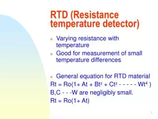
Calendar-Van Dusen Equation For platinum, the resistance temperature relationship is given by the Calendar-Van Dusen equation: (U.S. calibration curve, text p 248) For the U. S. calibration curve, a = 0.003851/°C ISAT 300
R1 R2 Vo Vs R4 RRTD RTD’s small resistance change requires • Bridge circuit: • Can detect small resistance changes • If R1=R4, RRTD= R2(Vs-2Vo)/(Vs+2Vo)(eq. 9.11) “Supply” Voltage ISAT 300
Circuits Used to Determine the Resistance of an RTD • Two-wire: Non-linear relationship between the measured voltage and the RTD resistance. • Three-wire: Better results. • Four-wire: Resistance is a linear function of the measured voltage. Four Wire Design ISAT 300
Example: An RTD probe has a resistance of 100 at 0oC. The Calendar-Van Dusen constants are = 0.00392, = 1.49, and = 0 for T > 0oC. What will be the resistance at 350oC. (RT=RRTD) Alternatively, we could use table 9.3 (p248) and obtain RT = 231.89 . ISAT 300
Summary • Thermocouples • Passive, non-linear, increase temperature increase voltages, big temperature range. • Types K and T are common devices. • Need reference temperature • Thermistors • Active, highly non-linear, increase temperature decrease resistance. • Medical use, not available above 300oC. • RTD’s • Requires a Bridge, Linear by nature. • High accuracy, use in industry & laboratory. • ALL: time constant of a first order system ISAT 300