Download
1 / 30
300 likes | 461 Vues
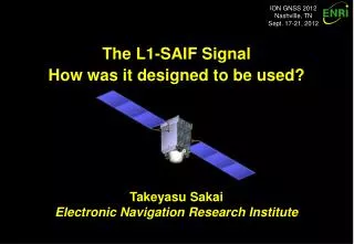
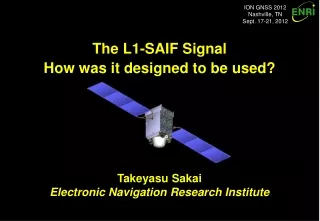
ION GNSS 2012 Nashville, TN Sept. 17-21, 2012. GPS/GLONASS Multi-Constellation SBAS Trial and Preliminary Results for East-Asia Region. Takeyasu Sakai, H. Yamada, and K. Hoshinoo, Electronic Navigation Research Institute. Introduction.

E N D
ION GNSS 2012 Nashville, TN Sept. 17-21, 2012 GPS/GLONASS Multi-Constellation SBAS Trial and Preliminary Results for East-Asia Region Takeyasu Sakai, H. Yamada, and K. Hoshinoo, Electronic Navigation Research Institute
Introduction • Combined use of GPS and GLONASS with SBAS augmentation: • GPS/GLONASS-capable receivers are now widely available; • SBAS (satellite-based augmentation system) is an international standard of the augmentation system; US WAAS, Japanese MSAS, and European EGNOS are already operational; • All operational SBAS are augmenting only GPS; • To improve availability of SBAS-augmented position information, a possible way is extending SBAS to support other constellation, e.g., GLONASS. • Possibility of Multi-Constellation SBAS (MC SBAS): • SBAS specification already has definitions necessary to augment GLONASS; • Investigating advantages of using GLONASS, we have implemented SBAS simulator capable of augmenting both GPS and GLONASS simultaneously; • It is confirmed that introducing GLONASS improves availability and robustness of position information especially where visibility is limited.
Geostationary Satellites GPS Satellites Augmentation Signal • Accuracy • Integrity • Ranging Ranging Signal Users Uplink Stations Ground Monitor Stations Concept of SBAS
Motivation SBAS GEO Augmentation Additional Constellation = GLONASS GPS constellation • Increase of augmented satellites improves availability of position solution; • Also possibly reduce protection levels; Improve availability of navigation; • Chance of robust position information at mountainous areas and urban canyons.
Part 1 GLONASS in the Current SBAS Standard
Current SBAS Standard • Already have definition of GLONASS: • The SBAS standard is documented by ICAO (International Civil Aviation Organization); • GLONASS L1 CSA (channel of standard accuracy) signal has already been described in the SBAS standard based on GLONASS ICD; • SBAS signal is also able to contain information on GLONASS satellites. • Differences from GPS in terms of SBAS augmentation: • FDMA signals; • Reference time and coordination system; • PRN mask numbers; • IOD along with corrections; and • Satellite position computation. The SBAS standard in the Annex to the Civil Aviation Convention
FDMA Signals • FCN (Frequency Channel Number): • GLONASS ICD defines FCN of –7 to +13; • Historically 0 to +13 were used; After 2005 the range of FCN shifts to –7 to +6; • FCN cannot be used for identification of satellites; two satellites share the same FCN. • Difference of carrier frequency affects: • Carrier smoothing: • Wave length per phase cycle is dependent upon carrier frequency. • Ionospheric corrections: • Ionospheric propagation delay is inversely proportional to square of carrier frequency. (GLONASS ICD v5.0)
Time and Coordinate Systems • GLONASS Time: • GLONASS is operating based on its own time system: GLONASS Time; • The difference between GPS Time and GLONASS Time must be taken into account for combined use of GPS and GLONASS; • The difference is not fixed and slowly changing: about 400ns in July 2012; • SBAS broadcasts the difference by Message Type 12; • GLONASS-M satellites are transmitting the difference as parameter tGPS in almanac (non-immediate) data: tGPS = tGPS− tGLONASS. • PZ-90 Coordinate System: • GLONASS ephemeris is derived based on Russian coordinate system PZ-90; • The relationship between WGS-84 • and the current version of PZ-90 • (PZ-90.02) is defined in the SBAS • standard as:
PRN Masks • PRN Mask: • SBAS transmits PRN mask information • indicating satellites which are augmented • by the SBAS; • PRN number has range of 1 to 210; • Up to 51 satellites out of 210 can be • augmented simultaneously by the single • SBAS signal; • But, 32 GPS + 24 GLONASS = 56 !!! • Solution: Dynamic PRN Mask • Actually, PRN mask can change; Controlled by IODP (Issue of Data, PRN Mask); • RTCA MOPS states this occurs “infrequently” while SBAS SARPS does not. • Change PRN mask dynamically to reflect the actual visibility of satellites from the intended service area. PRN definition for SBAS
Previous Ephemeris IODE=a Next Ephemeris IODE=b Time LTC IOD=b LTC IOD=a LTC IOD=a LTC IOD=a LTC IOD=b IOD (Issue of Data) • IOD indicator along with corrections: • LTC (Long-Term Correction) in SBAS Message Type 24/25 contains orbit and clock corrections; • Such corrections depend upon ephemeris data used for position computation; • IOD indicates which ephemeris data should be used in receivers. • IOD for GPS satellites: • For GPS, IOD is just identical with IODE of ephemeris data.
Previous Ephemeris Next Ephemeris Time Ephemeris Validity Interval LTC IOD=V2|L2 Ephemeris Validity Interval LTC IOD=V1|L1 V2 V1 L1 L2 IOD for GLONASS • IOD for GLONASS satellites: • GLONASS ephemeris has no indicator like IODE of GPS ephemeris; • IOD for GLONASS satellites consists of Validity interval (V) and Latency time (L) to identify ephemeris data to be used: • 5 MSB of IOD is validity interval, V; • 3 LSB of IOD is latency time, L. • User receivers use ephemeris data transmitted at a time within the validity interval specified by L and V.
Perturbation terms in ephemeris Satellite Position • GLONASS ephemeris data: • GLONASS transmits ephemeris information as position, velocity, and acceleration in ECEF; • Navigation-grade ephemeris is provided in 208 bits for a single GLONASS SV; • Broadcast information is valid for 15 minutes or more. • Numerical integration is necessary to compute position of GLONASS satellites; • Note: centripental acceleration is removed from transmitted information. • These terms can be computed for the specific position and velocity of SV; • GLONASS ICD A.3.1.2 gives the equations below (with some corrections).
.. x .. y .. z GLONASS Ephemeris
Part 2 Implementation and Experiment
User-side observations Network GPS observables User-Domain Receiver Software Position Error Software SBAS Simulator (RTWAD) Reference station observations Position Output SBAS Message Stream Software Implementation • ENRI’s software SBAS simulator: • ‘RTWAD’ runs on usual PC and Linux Workstations; • Generates SBAS message stream: one message per second; • Run modes: • Offline operation mode: for preliminary investigation using RINEX files; • Realtime operation mode: verification of actual performance with realtime raw data. • Needs user-domain receiver software to evaluate performance. • Upgrade for GLONASS (and QZSS): • Input module: RINEX observation and navigation files containing GLONASS; • Implemented GLONASS extension of SBAS standard; • User-domain receiver software is also upgraded to be GLONASS-capable; • QZSS is also supported as it is taken into account like GPS.
tcutover Cutover Transition time 180s PRN Mask (IODP=i) PRN Mask (IODP=i+1) FC FC LTC FC FC LTC FC FC LTC FC FC Corrections before cutover Corrections after cutover Dynamic PRN Mask • Dynamic PRN mask: • Changes PRN mask dynamically to reflect the actual visibility of satellites; • Set PRN masks ON for satellites whose pseudorange observations are available; Not based on prediction by almanac information not provided by RINEX; • Semi-dynamic PRN mask: Fix masks ON for GPS and QZSS, and change dynamically only for GLONASS to reduce receiver complexity. • Transition of PRN mask: • Periodical update of PRN mask: updates every 30 minutes; • Transition time 180s is given to users to securely catch the new PRN mask.
^ ^ BGLONASS BGPS True Time GLONASS System Time GPS System Time Receiver Time t tGLONASS tGPS tR Receiver clock for GPS satellites DtGLONASS DtGPS Time offset broadcast to users Receiver clock for GPS satellites -daGLONASS GLONASS Time Offset • Realtime computation: • Computes as the difference between receiver clocks for a group of GPS satellites (and QZSS) and the other group of GLONASS satellites; • Enough accuracy with a filter of long time constant; • Need no almanac information broadcast by GLONASS satellites; • Transmitted to users via Message Type 12 of SBAS.
Experiment: Monitor Stations • Recently Japanese GEONET began to provide GLONASS and QZSS observables in addition to GPS; • Currently more than 150 stations are GLONASS/QZSS-capable; • Data format: RINEX 2.12 observation and navigation files. • For our experiment: • 8 sites for reference stations; Reference Station (1) to (8) • 3 sites for evaluation. User Station (a) to (c) • Period: 12/7/18 – 12/7/20 (3 days).
PRN Mask Transition QZSS • Reflecting our implementation, PRN mask is updated periodically at every 30 minutes; • Semi-dynamic PRN mask: GPS and QZSS satellites are always ON in the masks; • PRN masks for GLONASS satellites are set ON if the satellite are visible and augmented; • Stair-like shape: because the slot number of GLONASS satellites are assigned increasingly along with the orbit. • IODP (issue of Data, PRN Mask) indicates change of PRN mask. GLONASS GPS
Elevation Angle GPS GLONASS QZSS PRN Mask Transition 5 deg @ Tokyo • Rising satellites appear at 5-12 deg above the horizon; Latency due to periodical update of PRN mask; • However, GPS satellites also have similar latency; Not a major problem because low elevation satellites contribute a little to improve position accuracy.
# of Satellites vs. Mask Angle 17 SVs 9.8 SVs 7.4 SVs @ User (b) • Introducing GLONASS satellites increases the number of satellites in roughly 75%; • QZSS increases a satellite almost all day by only a satellite on the orbit, QZS-1 "Michibiki" • Multi-constellation with QZSS offers 17 satellites at 5 deg and 9.8 satellites even at 30 deg.
Availability vs. Mask Angle 100% Availability @ User (b) • The number of epochs with position solution decreases with regard to increase of mask angle; • Multi-constellation with QZSS achieves 100% availability even for 40 deg mask.
DOP vs. Mask Angle HDOP = 2.3 @ User (b) • GLONASS-only users suffer poor geometries; • Multi-constellation with QZSS offers HDOP of 2.3 even for 40 deg mask.
User Position Error: Mask 5deg • GPS+GLO+QZS: 0.310m RMS of horizontal error at user location (b); • Looks some improvement by using multi-constellation.
User Position Error: Mask 30deg • GPS+GLO+QZS: 0.372m RMS of horizontal error at user location (b); • Multi-constellation offers a good availability even for 30 deg mask.
RMS Error vs. Mask: User (a) 0.528m @ User (a) • Northernmost user location; • Multi-constellation provides robust position information through mask angle of 5 to 40 deg.
RMS Error vs. Mask: User (b) 0.602m @ User (b) • User location near the centroid of reference station network; • For vertical direction, 10 deg mask shows the best accuracy except GLONASS only case.
RMS Error vs. Mask: User (c) 0.588m @ User (c) • Southernmost user location; • There is little dependency upon user location; possibly because ionosphere condition is quiet for the period of this experiment.
Vertical Protection Level Reduce GPS only GPS+GLO+QZS • Protection levels mean the confidence limit at 99.99999% confidential level; • In these chart, unsafe condition exists if there are plots at the right of the diagonal line; • GLONASS reduces VPL; Means improvement of availability of navigation.
Conclusion • Combined use of GPS and GLONASS with SBAS: • Multi-constellation SBAS, capable of augmenting both GPS and GLONASS, and additionally QZSS, is implemented and tested successfully; • Potential problems and solutions on realizing a multi-constellation SBAS based on the current standard were investigated; • It is confirmed that the performance of SBAS-aided navigation is certainly improved by adding GLONASS, especially when satellite visibility is limited; • Adding GLONASS also reduces protection levels and thus improves availability of navigation. • Ongoing and future works: • Support of realtime operation mode; • Realtime operation test broadcasting augmentation information for both GPS and GLONASS on QZSS L1-SAIF augmentation channel; • Use GLONASS observables in generation of ionospheric correction; • Mixed use of different types of receiver for reference stations; • Further extension to support Galileo.