Download
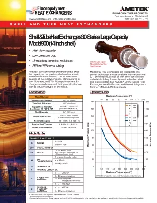
1 / 33
480 likes | 1.11k Vues
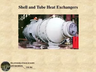
Shell and Tube Heat Exchangers. Goals: By the end of today’s lecture, you should be able to: describe the common shell-and-tube HE designs draw temperature profiles for parallel and counter-current flow in a shell-and-tube HE

E N D
Goals: • By the end of today’s lecture, you should be able to: • describe the common shell-and-tube HE designs • draw temperature profiles for parallel and counter-current flow in a shell-and-tube HE • calculate the true mean temperature difference for a shell-and-tube HE (use FG chart) • make heat transfer calculations for shell-and-tube HEs • describe how the inside and outside heat transfer coefficients are determined for shell-and-tube HEs • use the Donohue equation to estimate ho in a multiple pass heat exchanger • make heat transfer calculations for multiple pass shell-and-tube heat exchangers
Outline: • I. Review • II. Shell-and-tube equipment • III. Rate equation and DTTM • IV. Example Problem - FG for multiple pass HE • V. Heat transfer coefficients • VI. Example Problem - Handout
I. Review Last time, we reviewed heat transfer in double pipe (concentric pipe) heat exchangers. We considered cases of parallel and countercurrent flow of the hot and cold fluids in the concentric pipe design. The basic equations required in the design of a heat exchanger are the enthalpy balances on both fluid streams and a rate equation that defines the heat transfer rate.
Enthalpy balances for fluids without phase change: (hot stream) and (cold stream) If a phase change occurs (the hot stream is condensed), then the heat of condensation (vaporization) must be accounted for: In most applications, the heat gained by the cold stream can be assumed to equal the heat lost by the hot stream (i.e., qh = qc).
The rate of heat transfer for a concentric pipe heat exchanger with parallel or countercurrent flow can be written as: or where DTTM is the true mean temperature difference. For concentric pipe heat exchangers, the true mean temperature difference is equal to the log mean temperature difference (DTLM).
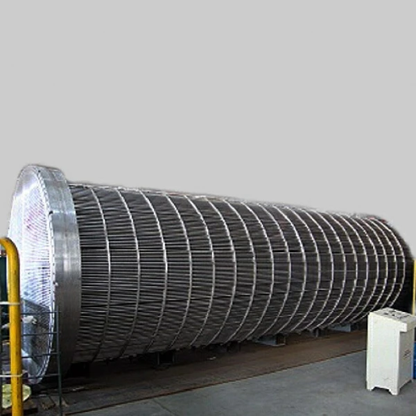
II. Shell-and-Tube Equipment Concentric Pipe vs. Shell & Tube Heat Exchangers: The simple double pipe heat exchanger is inadequate for flow rates that cannot readily be handled in a few tubes. Double pipe heat exchangers are not used for required heat exchange areas in excess of 100-150 ft2. Several double pipe heat exchangers can be used in parallel, but it proves more economical to have a single shell serve for multiple tubes.
Shell-and-tube heat exchangers are described based on the number of passes the shell-side and tube-side fluids must undergo. Exchangers are listed as 1-1, 1-2, 2-4, etc. in which the first number signifies the number of passes for the shell-side fluid and the second number refers to the tube-side fluid.
Baffles How do baffles help? Where are they installed and which fluid is directly affected? Common practice is to cut away a segment having a height equal to one- fourth the inside diameter of the shell. Such baffles are called 25 percent baffles.
The RODbaffle heat exchanger design (Phillips Petroleum Co.)
Tube sizes Tubes Standard tube lengths are 8, 12, 16 and 20 ft. Tubes are drawn to definite wall thickness in terms of BWG and true outside diameter (OD), and they are available in all common metals.
Tube Pitch The spacing between the tubes (center to center) is referred to as the tube pitch (PT). Triangular or square pitch arrangements are used. Unless the shell side tends to foul badly, triangular pitch is Used. Dimensions of standard tubes are given in the Handout and in MSH Appendix 6.
III. Rate equation and DTTM The rate equation for a shell-and-tube heat exchanger is the same as for a concentric pipe exchanger: However, Ui and DTTM are evaluated somewhat differently for shell-and-tube exchangers. We will first discuss how to evaluate DTTM and then a little later in the notes we will discuss how to evaluate Ui for shell-and-tube exchangers. In a shell-and-tube exchanger, the flow can be single or multipass. As a result, the temperature profiles for the two fluids in a shell-and-tube heat exchanger are more complex, as shown below.
Computation of DTTM: For the concentric pipe heat exchanger, we showed the following (parallel and countercurrent flow): DTTM = When a fluid flows perpendicular to a heated or cooled tube bank, and if both of the fluid temperatures are varying, then the temperature conditions do not correspond to either parallel or countercurrent. Instead, this is called crossflow. DTlm
The factor Z is the ratio of the fall in temperature of the hot fluid to the rise in temperature of the cold fluid. The factor hH is the heating effectiveness, or the ratio of the actual temperature rise of the cold fluid to the maximum possible temperature rise obtainable (if the warm-end approach were zero, based on countercurrent flow). From the given values of hH and Z, the factor FG can be read from the text book figures:
Therefore, as with the concentric pipe heat exchanger, the true mean temperature difference for the 1-1 exchanger is equal to the log mean temperature difference (DTLM). For multiple pass shell-and-tube designs, the flow is complex and the DTLM is less than that for a pure countercurrent design. We must account for the smaller temperature driving force using a correction factor, FG, which is less than 1 and typically greater than 0.8. The rate of heat transfer in multiple pass heat exchangers is written as: where DTLM is the log mean temperature difference for pure countercurrent flow
Textbook Figures 15.6 a, b 1-2 exchangers 2-4 exchangers
Ten Minute Problem -- FG for multiple pass HE • For a 2-4 heat exchanger with the cold fluid inside the tubes and the following • temperatures: • Tca = 85°F Tha = 200°F • Tcb = 125°F Thb = 100°F • (a) What is the true mean temperature difference? • (answer D TTM = 31.7°F) • (b) What exchanger area is required to cool 50,000 lbm/hr of product • (shell-side fluid) if the overall heat transfer coefficient is 100 Btu/hr-ft2-°F • and Cp for the product is 0.45 Btu/lbm-°F? • (answer A = 710 ft2)
V. Heat transfer coefficients In a shell-and-tube exchanger, the shell-side and tube-side heat transfer coefficients are of comparable importance and both must be large if a satisfactory overall coefficient is to be attained.
Gb Gc Gb
Exchanger Fouling Electron microscope image showing fibers, dust, and other deposited material on a residential air conditioner coil and a fouled water line in a water heater.