Download

1 / 12
200 likes | 611 Vues
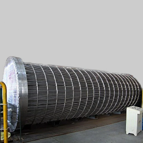
SHELL AND TUBE HEAT EXCHANGER. SHELL AND TUBE HEAT EXCHANGER. With respect to tube layout in the tube bundle, the tubes are commonly laid out on a square pattern or on a triangular pattern .

E N D
SHELL AND TUBE HEAT EXCHANGER With respect to tube layout in the tube bundle, the tubes are commonly laid out on a square pattern or on a triangular pattern. The shortest center-to-center distance between adjacent tubes in either arrangement is defined as Tube Pitch (PT). The shortest distance between any two tubes is called tube clearance (PD).
In most shell and tube exchangers, the tube pitch for economic reasons is maintained between 1.25 and 1.50 times the tube diameter. It is recommended that the tube clearance should not be less than one-fourth of the tube diameter with a minimum clearacne of no less than 0.0048 m.
Although a square pitch pattern has the advantage of easier external cleaning, the triangular pitch pattern is often preferred because it permits the use of more tubes and hence results in more surface area in a given shell diameter.
The standard length of tubes in shell and tube heat exchangers is normally 2.44, 3.66 or 4.88 m. These tubes are available in a variety of different diameters and wall thicknesses. A tube diameter of 0.019 or 0.0254 m OD is the most common, but outside diameters up to 0.038 m are used in many industrial applications. Tube wall thickness is usually specified by the Birmingham Wire Gauge (BWG). Normal pipe sizes apply to the shell for diameters up to 0.710 m. In general, a shell thickness of 0.0095 m is used for shell diameters between 0.305 and 0.710 m.
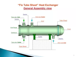
BAFFLES The function of the baffle in a shell and tube heat exchanger is to direct the flow across the tube bundle as well as to support the tubes from sagging and possible vibration. The presence of baffles in the shell side of such exchangers increases the pressure drop on the shell side; however, the advantage of better mixing of the fluid with increased turbulence more than offsets the pressure drop disadvantage. In general, baffles should not be spaced closer than one-fifth of the inner shell diameter.
BAFFLES The most common type of baffle used in shell and tube heat exchangers is the segmental baffle. Many segmental baffles have a baffle height that is 75 percent of the inside diameter of the shell. This arrangement is designated as a segmental baffle with a 25 percent cut. The ratio of baffle spacing to baffle cut is a critical design parameter for determining a realistic pressure drop on the shell side of the exchanger. The thickness of the baffles should be at least twice the thickness of the tube walls and is generally in the range of 0.003 to 0.006m.