Download
1 / 2
20 likes | 88 Vues
This study addresses the comparison of CFI over shell and tube heat exchanger. Helical coils have been used in<br>place of baffles as well as of tubes by which, cost is decreased for the same heat exchanger. Normal CFI gives<br>higher heat transfer rates, heat transfer coefficient and less pressure drop up to certain range of Reynolds no.<br>Although everything goes in favor of CFI but simultaneously it has a drawback that at higher Reynolds no. its<br>thermal characteristics get down. <br>

E N D
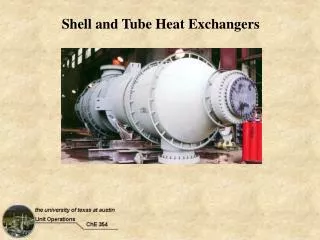
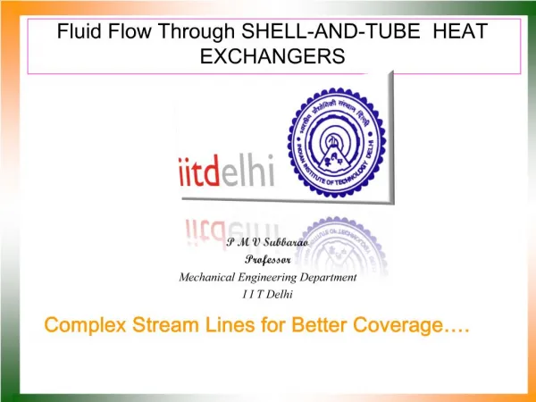
Available online www.jocpr.com Journal of Chemical and Pharmaceutical Research, 2013, 5(6):12-13 ISSN : 0975-7384 CODEN(USA) : JCPRC5 Research Article Advantages of coiled flow inverter over shell and tube heat exchanger Srashti Dwivedi and Priyanka Jain Chemical department, ITM Universe, Gwalior(MP) _____________________________________________________________________________________________ ABSTRACT This study addresses the comparison of CFI over shell and tube heat exchanger. Helical coils have been used in place of baffles as well as of tubes by which, cost is decreased for the same heat exchanger. Normal CFI gives higher heat transfer rates, heat transfer coefficient and less pressure drop up to certain range of Reynolds no. Although everything goes in favor of CFI but simultaneously it has a drawback that at higher Reynolds no. its thermal characteristics get down. Keywords: CFI, Helical coils, Heat transfer, Reynolds, Baffles _____________________________________________________________________________________________ INTRODUCTION Heat exchangers are commonly used for heat transfer between two or more fluids of different temperatures in refrigeration and air conditioning system, heat recovery processes , chemical reactors, food and dairy processes and other thermal plants. Due to their their compact structure and high HT coefficient, curved tubes are one of the passive HT enhancement techniques are widely used in various industrial applications [4]. These are also used in nuclear industry, food industry etc. [2,5] . The modification of the flow in helically coiled tubes is due to the centrifugal forces. The curvature of the tube produces a secondary flow field with a circulatory motion, which causes the fluid particles to move toward the core region of the tube. Cengiz yildiz presents the effect of fluid rotation on the heat transferand pressure drop in double pipe heat exchanger. The effect of propellers placed inside of tube rotates freely due to fluid flowing inside of tube of double pipe heat exchanger. This propeller increases the heat transfer but they increase pressure drop [6]. Different types of baffles were used to increase turbulence. Experimentally observed the tube side pressure drop and heat transfer. The new impirical correlation developed for friction factor and heat transfer [5,1]. It was found that the pressure drop increase with increase the no. of bends [3]. EXPERIMENTAL SECTION The experimental work is carried out in counter current mode operation with hot fluid in the tube side and cold fluid in the shell side in the present work chaotic flow is generated by the flow of flow inversion by inserting 90º bends between regular coiled tubes .This geometrical perturbation is the main cause of flow inversion phenomenon. The purpose of the study is to determine experimentally the hydrodynamics and fully developed heat transfer variations with flow rate in the CFI(coiled flow inverter) as heat exchanger. Experiments on the heat exchanger were carried out in order to obtain a measure of their relative performance in terms of heat transfer and pressure drop and the results obtained were compared with the data reported in the literature for coiled tube. Since the experiments 12
J. Chem. Pharm. Res., 2013, 5(6):12-13 Srashti Dwivedi and Priyanka Jain ______________________________________________________________________________ were carried out over a range of Reynolds no. therefore the comparison was made based on the inner heat transfer experimental data analysis were also carried out in shell side of the heat exchanger. PROCEDURE:- •Experiments are conducted under steady state conditions with compressed air in the tube side and either cooling water or ambient air in the shell side as the working fluids. •The flow rate in the tube side was varied over a range of 30-320 l/h for a constant shell side flow rate. The shell side flow rates were varied from 800-3000l/h. •Temperature data were recorded at every 10s. Temperature measurements from the 300s of the stable system were used , with temperature reading fluctuations with in ±0.15ºC. Through the type T thermocouples had limits of error of 0.5ºC, when placed in a common water solution the readings at steady state were all within ±0.1ºC. All the thermocouples were constructed from the same roll of thermocouple wire,and hence the repeatability of temperature readings is high. •Similarly for the heat transfer study in the shell side , the tube side flow rate was kept constant at 220l/h and variation in the shell side, the tube side flow rate is made. At the inlet of the outer tube of the heat exchanger the cooling water temperature was 26º-28ºC, and it rises by 4º-5ºC at the outlet of the outer tube. •During the experiments the ambient temperature was 27º-28ºC, therefore there was not much heat loss from the outer wall of the heat exchanger. PREPARATION OF CFI:- Thick walled transparent PVC tubing was used to prepare the coils the PVC tubes were wound around a square shaped frame that comprised of cylindrical rods. Coil diameter was varied over a range of 0.067-0.2 m and the internal diameter of tube was varied over a range of 0.005-0.015 m. The range of the curvature ratio which is defined as D/d was determine to be 6.7-20 and dimesionless pitch was determine to be 1-2.5. The straight unfolded length of the was kept at a length of 27. The angle at the bend was 90º, equally spaced before and after the bend. The complete unit consisted of square shaped subunits that have been joined together, keeping the bend angle as constraint. The coils were fixed and carefully tightened with clamps to avoid deformation of tubes. Fabrication of the equipment was done at instrument design development centre, IIT Delhi. RESULTS AND DISCUSSION These experiments were performed for an air water system in a CFI. The liquid flow rate was varied from 3.33*10-6 m3/s-1.0*10-3 m3/s, and the gas flow rate was changed from 8.33*10-5 m3/s-1.0*10-3m3/s. The physical properties of the fluids were taken under ambient temperature and pressure conditions. The new design of CFI as heat exchanger is presented which comprised of coils and 90º bends the insertion of 90º bends between the coil tubes generates the phenomenon of flow inversions that increases the mixing betwewn the fluid elements and enhance the heat transfer. Experimental study was made over a large range of Reynolds no. from 1000- either cooling water or ambient air. It was observed tha at low Reynolds no. the heat transfer was 25% higher and at higher Reynolds no. it was 12% higher as compared to the coil tubee data reported in the literature. This apparatus will be a valuable addition to the thermal engineering laboratory for years to come. Acknowledgements I would deeply indebted to moral support and encouragement of my all well-wishers whose perennial inspiration and incessant help kept me at right track at all times and constant encouragement to fulfill my desire. REFERENCES [1] Kumar V, Saini S., Chemical engineering Science , 2006, 61, 4403-4416. [2] Prabhajan D G., Ragbavan GSV, International communications heat mass transfer, 2002, 29(2), 185-191. [3] Rane M.V., Tandele M.S., Applied thermal engineering , 2005, 25, 2715-2729. [4] S.S. Pawar, Vivek K., Journal of scientific and Industrial research, 2011, 70, 835-843. [5] Sharma M, Kumar V, Chemical engineering science, 2006, 62, 2386-2396. [6] Yildiz C, Bicer Y, Applied energy, 1996, 549(1), 49-56. 13