Capacitive Analysis in AC Circuits: Reactance, Impedance, and Current Calculation
This assessment involves the calculation of various electrical parameters for a 5 µF capacitor with a voltage of 30cos(4000t + 25°). Key tasks include determining the capacitive reactance (XC), the impedance (ZC) of the capacitor, the phasor current (I), and the steady-state expression for the current (i(t)). Using the appropriate formulas, we derive that XC = -50Ω, ZC = -j50Ω, I = 0.6/115°, and the corresponding current expression is i(t) = 0.6cos(4000t + 115°) A, illustrating essential AC circuit concepts.

Capacitive Analysis in AC Circuits: Reactance, Impedance, and Current Calculation
E N D
Presentation Transcript
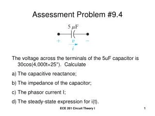
Assessment Problem #9.4 • The voltage across the terminals of the 5uF capacitor is 30cos(4,000t+25°). Calculate • The capacitive reactance; • The impedance of the capacitor; • The phasor current I; • The steady-state expression for i(t). ECE 201 Circuit Theory I
a) XC = -1/ωC = -1/(4,000)(5X10-6) = -50Ω; b) ZC = -j50Ω; c) I = jωCV = j(4,000)(5X10⁻⁶)(30/25°) = 0.6/(90°+25°) = 0.6/115° A. d) i(t) = 0.6cos(4,000t + 115°) A. ECE 201 Circuit Theory I