Unit 6 Industrial Robotics
Unit 6 Industrial Robotics. Sections: Robot Anatomy Robot Control Systems End Effectors Industrial Robot Applications Robot Programming. Industrial Robot Defined. A general-purpose, programmable machine possessing certain anthropomorphic characteristics Hazardous work environments

Unit 6 Industrial Robotics
E N D
Presentation Transcript
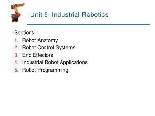
Unit 6 Industrial Robotics Sections: • Robot Anatomy • Robot Control Systems • End Effectors • Industrial Robot Applications • Robot Programming
Industrial Robot Defined A general-purpose, programmable machine possessing certain anthropomorphic characteristics • Hazardous work environments • Repetitive work cycle • Consistency and accuracy • Difficult handling task for humans • Multishift operations • Reprogrammable, flexible • Interfaced to other computer systems
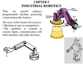
Robot Anatomy • Manipulator consists of joints and links • Joints provide relative motion • Links are rigid members between joints • Various joint types: linear and rotary • Each joint provides a “degree-of-freedom” • Most robots possess five or six degrees-of-freedom • Robot manipulator consists of two sections: • Body-and-arm – for positioning of objects in the robot's work volume • Wrist assembly – for orientation of objects Link3 Joint3 End of Arm Link2 Link1 Joint2 Joint1 Link0 Base
Manipulator Joints • Translational motion • Linear joint (type L) • Orthogonal joint (type O) • Rotary motion • Rotational joint (type R) • Twisting joint (type T) • Revolving joint (type V)
Joint Notation Scheme • Uses the joint symbols (L, O, R, T, V) to designate joint types used to construct robot manipulator • Separates body-and-arm assembly from wrist assembly using a colon (:) • Example: TLR : TR • Common body-and-arm configurations …
Polar Coordinate Body-and-Arm Assembly • Notation TRL: • Consists of a sliding arm (L joint) actuated relative to the body, which can rotate about both a vertical axis (T joint) and horizontal axis (R joint)
Cylindrical Body-and-Arm Assembly • Notation TLO: • Consists of a vertical column, relative to which an arm assembly is moved up or down • The arm can be moved in or out relative to the column
Cartesian Coordinate Body-and-Arm Assembly • Notation LOO: • Consists of three sliding joints, two of which are orthogonal • Other names include rectilinear robot and x-y-z robot
Jointed-Arm Robot • Notation TRR:
SCARA Robot • Notation VRO • SCARA stands for Selectively Compliant Assembly Robot Arm • Similar to jointed-arm robot except that vertical axes are used for shoulder and elbow joints to be compliant in horizontal direction for vertical insertion tasks
Wrist Configurations • Wrist assembly is attached to end-of-arm • End effector is attached to wrist assembly • Function of wrist assembly is to orient end effector • Body-and-arm determines global position of end effector • Two or three degrees of freedom: • Roll • Pitch • Yaw • Notation :RRT
Example • Sketch following manipulator configurations • (a) TRT:R, (b) TVR:TR, (c) RR:T. Solution:
Joint Drive Systems • Electric • Uses electric motors to actuate individual joints • Preferred drive system in today's robots • Hydraulic • Uses hydraulic pistons and rotary vane actuators • Noted for their high power and lift capacity • Pneumatic • Typically limited to smaller robots and simple material transfer applications
Robot Control Systems • Limited sequence control – pick-and-place operations using mechanical stops to set positions • Playback with point-to-point control – records work cycle as a sequence of points, then plays back the sequence during program execution • Playback with continuous path control – greater memory capacity and/or interpolation capability to execute paths (in addition to points) • Intelligent control – exhibits behavior that makes it seem intelligent, e.g., responds to sensor inputs, makes decisions, communicates with humans
Robot Control System Cell Supervisor Level 2 Controller & Program Level 1 Joint 1 Joint 2 Joint 3 Joint 4 Joint 5 Joint 6 Sensors Level 0
End Effectors • The special tooling for a robot that enables it to perform a specific task • Two types: • Grippers – to grasp and manipulate objects (e.g., parts) during work cycle • Tools – to perform a process, e.g., spot welding, spray painting
Industrial Robot Applications • Material handling applications • Material transfer – pick-and-place, palletizing • Machine loading and/or unloading • Processing operations • Welding • Spray coating • Cutting and grinding • Assembly and inspection
Robotic Arc-Welding Cell • Robot performs flux-cored arc welding (FCAW) operation at one workstation while fitter changes parts at the other workstation
Robot Programming • Leadthrough programming • Work cycle is taught to robot by moving the manipulator through the required motion cycle and simultaneously entering the program into controller memory for later playback • Robot programming languages • Textual programming language to enter commands into robot controller • Simulation and off-line programming • Program is prepared at a remote computer terminal and downloaded to robot controller for execution without need for leadthrough methods
Leadthrough Programming • Powered leadthrough • Common for point-to-point robots • Uses teach pendant • Manual leadthrough • Convenient for continuous path control robots • Human programmer physical moves manipulator
Leadthrough Programming Advantages • Advantages: • Easily learned by shop personnel • Logical way to teach a robot • No computer programming • Disadvantages: • Downtime during programming • Limited programming logic capability • Not compatible with supervisory control
Robot Programming • Textural programming languages • Enhanced sensor capabilities • Improved output capabilities to control external equipment • Program logic • Computations and data processing • Communications with supervisory computers
Coordinate Systems World coordinate system Tool coordinate system
Motion Commands MOVE P1 HERE P1 - used during lead through of manipulator MOVES P1 DMOVE(4, 125) APPROACH P1, 40 MM DEPART 40 MM DEFINE PATH123 = PATH(P1, P2, P3) MOVE PATH123 SPEED 75
Interlock and Sensor Commands Interlock Commands WAIT 20, ON SIGNAL 10, ON SIGNAL 10, 6.0 REACT 25, SAFESTOP Gripper Commands OPEN CLOSE CLOSE 25 MM CLOSE 2.0 N
Example A robot performs a loading and unloading operation for a machine tool as follows: • Robot pick up part from conveyor and loads into machine (Time=5.5 sec) • Machining cycle (automatic). (Time=33.0 sec) • Robot retrieves part from machine and deposits to outgoing conveyor. (Time=4.8 sec) • Robot moves back to pickup position. (Time=1.7 sec) Every 30 work parts, the cutting tools in the machine are changed which takes 3.0 minutes. The uptime efficiency of the robot is 97%; and the uptime efficiency of the machine tool is 98% which rarely overlap. Determine the hourly production rate.
Solution Tc = 5.5 + 33.0 + 4.8 + 1.7 = 45 sec/cycle Tool change time Ttc = 180 sec/30 pc = 6 sec/pc Robot uptime ER = 0.97, lost time = 0.03. Machine tool uptime EM = 0.98, lost time = 0.02. Total time = Tc + Ttc/30 = 45 + 6 = 51 sec = 0.85 min/pc Rc = 60/0.85 = 70.59 pc/hr Accounting for uptime efficiencies, Rp = 70.59(1.0 - 0.03 - 0.02) = 67.06 pc/hr