
Simple Machines Practice Workshop: Understanding Force and Torque in Levers
E N D
Presentation Transcript
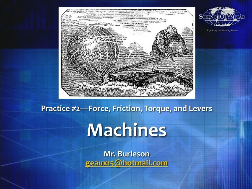
Machines Practice #2—Force, Friction, Torque, and Levers Mr. Burleson geaux15@hotmail.com
Agenda • Introduction and Rules • Basics of Machines • Machines Practical • Homework 2
Introduction and Rules • Come prepared to practices with completed homework and all your questions • Listen and participate. • Be willing to study on your own and do more work than assigned 3
Machines (B)Rules • Team of 2 • No Eye Protection Required • Device must be impounded • Part 1 (Written Test) • 45% of score • Simple Machine Concepts • Simple Machine Calculations • Simple Machine History is no longer included • Part 2 (Device Testing) • 55% of score • Two Ratio Scores (15% each) • One Time Score (15%) • Chart Score (10%) • Only five types of machines • Levers (all three classes) • Inclined Plane • Wedge • Pulley (up to two double pulleys) • Wheel and Axle • Prohibited topics • Compound machines • Dynamic Calculations • Material Strengths • Potential/Kinetic Energy • Coefficient of Friction • Screw Simple Machines • Angle of Repose 4 4
Machines (C)Rules • Team of 2 • No Eye Protection Required • Device must be impounded • Part 1 (Written Test) • 45% of score • Sim/Compound Machine Concepts • Sim/Compound Machine Calcs • Sim/Compound Machine History is no longer included • Part 2 (Device Testing) • 55% of score • Two Ratio Scores (15% each) • One Time Score (15%) • Chart Score (10%) • All six types of simple machines • Levers (all three classes) • Inclined Plane • Wedge • Pulley (up to two double pulleys) • Wheel and Axle • Screw • Prohibited topics • Dynamic Calculations • Material Strengths • Angle of Repose 5
Scoring forMachines • Exam Score (ES) is worth maximum 45 points (45 points awarded to highest test score) • Time Score (TS) = ((240-time)/240*15 points (max 15 points) • Ratio Score (R1 and R2)=(1-(abs(AR-MR)/AR))*15 points (max 2x15 = 30 points) • Chart Score (CS) is worth 10 points (max 10 points) • 2 points for including data spanning the possible mass range • 2 points for including at least 10 data points in each data series • 2 points for proper labeling (e.g. title, team name, units) • 2 points for distinct graphs (0.5 points each up to 2 points) • 2 point for including a labeled device diagram • Violations • Competition violate TS, R1, and R2 are multiplied by 0.9 • Construction violation, if resolved during competition block or miss impound TS, R1, and R2 are multiplied by 0.7 • Team with no device, no ratio estimate or do not make an HONEST attempt TS, R1, and R2 all marked zero • Final Score (FS)=ES+MS+TS+CS (maximum of 100 points) • Tie Breakers • Best ES score • Best TS score • Best R1 • Best R2 6
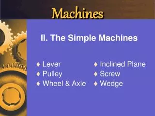
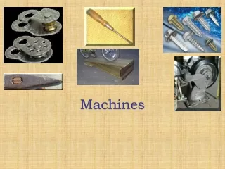
Basics of Simple Machines • Lever • Inclined Plane • Wheel and Axle • Wedge • Pulley • Screw, not included in Machines (B)
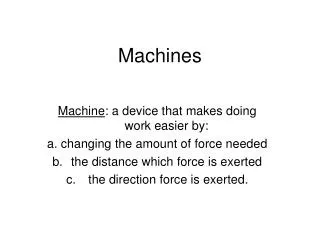
Basic Definition of Simple Machines • A simple machine is an elementary device that has a specific movement (often called a mechanism), which can be combined with other devices and movements to form a machine. • The idea of a "simple machine" originated with the Greek philosopher Archimedes around the 3rd century BC, who studied the "Archimedean" simple machines: lever, pulley, and screw • Thus simple machines are considered to be the "building blocks" of more complicated machines. • A bicycle has wheels, levers, and pulleys
Mechanical Advantage • A machine has an applied force (or effort) that works against a load force. • If there are no friction losses, the work done on the load is equal to the work done by the applied force. • This allows an increase in the output force at the cost of a proportional decrease in the distance moved by the load. • The ratio of the output force to the input force is the mechanical advantage of the machine.
Efficiency • Machines lose energy through friction, deformation and wear, which is dissipated as heat. • This means the power out of the machine is less than power in. • The ratio of power out to power in is the efficiency η of the machine, and is a measure of the energy losses.
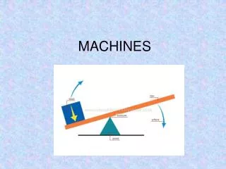
What is a Lever? • A lever is a machine consisting of a beam or rigid rod pivoted at a fixed hinge, or fulcrum • The word comes from the French lever, "to raise", cf. a levant. • A lever amplifies an input force to provide a greater output force, which is said to provide leverage. • The ratio of the output force to the input force is the ideal mechanical advantage of the lever.
Building a Good Lever Low Loss Fulcrum Point • Ensure device fits into the bound box, 1m x 1m x 0.5m • Ensure device is sturdy • Ensure Division B Beam is less than 80cm no matter how measured (include anything on the ends) • Ensure both Division C beams are less than 40cm no matter how measured (include anything on the ends) • Add counterweight to balance the lever (may need to be redone prior to each measurement) and use a level • Make sure it can handle the masses (15cm x 15cm x 20cm) • Reduce any sources of loss in your lever system • Strong, unbending, but very light parts especially the beams, strings, etc. • For rotating points reduce friction through metal/metal interfaces, bearings, and lubrication • Put blank paper to mark different ratio results and write clearly based upon multiple measurements • Build a transport box for protection and impound (have it fit within the bound box or 1m x 1m x 0.5m) • Practice first for accuracy and then over time for increased speed • Initial determination of which one is heavier and which one is lighter is critical for precise measurements Counterweight Ratio labels https://slideplayer.com/slide/1544490/
Building a Good Lever(cont) Low Loss Fulcrum Point • Beam can be as simple as a meterstick or yard stick (lightweight and won’t bend) • Make sure that there is enough room for the masses to hang underneath (over 20 cm height, with maximum 15 cm width and 15 cm length). • Focus on the Regionals ratios first • Division B 4:1 and Division C 8:1 • Get the beam well balanced first • Make sure it can handle the full ratios • Get all your Chart Score • Draw your diagram • Make multiple measurements to show you your marked your ratio labels and do your charts • If you make it to State, move your fulcrum point and remeasure for those ratios • Division B 5.5:1 and Division C 10:1 • Practice for accuracy first and after you have 99% accuracy start working on speed by dividing tasks and practicing Counterweight Ratio labels https://slideplayer.com/slide/1544490/
Classes of Levers • Class 1: Fulcrum in the middle: the effort is applied on one side of the fulcrum and the resistance on the other side • A crowbar or a pair of scissors. • Class 2: Resistance in the middle: the effort is applied on one side of the resistance and the fulcrum is located on the other side. • A wheelbarrow, a nutcracker, a bottle opener or the brake pedal of a car. Mechanical advantage is greater than 1. • Class 3: Effort in the middle: the resistance is on one side of the effort and the fulcrum is located on the other side • A pair of tweezers or the human mandible. Mechanical advantage is less than 1.
IMA of Lever/Law of the Lever • If a and b are distances from the fulcrum to points A and B and let the force FA applied to • A is the input and the force FB applied at B is the output, the ratio of the velocities of points A and B is given by a/b, so we have the ratio of the output force to the input force, or mechanical advantage, is given by
Practical • Get a ruler or meter/yardstick—this is your lever arm • Balance the lever arm on something immobile (like your finger or anything with an edge pointing up • Where does it balance? • What happens when you move it from away from the balance point? • Now try to balance something that fits on the ruler or meter stick (like an eraser, something that won’t roll) • Put one on each side of the balanced lever • Put one closer than the other • Put them the same distance apart 16
What is a pulley? • A pulley is a wheel on an axle that is designed to support movement of a cable or belt along its circumference. • Pulleys are used in a variety of ways to lift loads, apply forces, and to transmit power. • Also called a block, sheave, or drum and may have a groove between two flanges around its circumference. • The drive element of a pulley system can be a rope, cable, belt, or chain that runs over the pulley inside the groove.
Pulleys linked by acircular chain or belt • Below is a pulley and belt system, which operates like a Wheel and Axle, but is classified a pulley system • Pulleys have different axles • Motion is circular/angular not linear • The IMA is dependent upon the ratio of the wheels/pulleys versus the number of lines connecting • One wheel/pulley is the driver and one is the driven
What is a Wheel and Axle • Wheel and Axle is a simple machine that is generally considered to be a wheel attached to an axle so that these two parts rotate together in which a force is transferred from one to the other. • The IMA is caused by the difference in radius between the wheel and axle • Either the Wheel or Axle may be the driving force
Gears are also a Wheel and Axle type of machine • A gear or cogwheel is a rotating machine part having cut teeth, or cogs, which mesh with another toothed part in order to transmit torque • Usually the teeth on the one gear of identical shape, and often also with that shape (or just width) on the other gear. • Two or more gears working in tandem are called a transmission and can produce a mechanical advantage through a gear ratio and thus may be considered a simple machine.
What is a Wedge? • A wedge is a triangular shaped tool, a compound and portable inclined plane, and one of the six classical simple machines. • It can be used to separate two objects or portions of an object, lift up an object, or hold an object in place. • It functions by converting a force applied to its blunt end into forces perpendicular (normal) to its inclined surfaces.
What is an Inclined Plane? • An inclined plane is a flat supporting surface tilted at an angle, with one end higher than the other, used as an aid for raising or lowering a load • Can include friction (static only) for Complex Machines (C) or be frictionless for either event
What is a Screw? • A screw is a mechanism that converts rotational motion to linear motion, and a torque (rotational force) to a linear force • Last simple machine invented, appeared first in ancient Greece • It can be seen that the mechanical advantage of a screw depends on its lead, P • The smaller the distance between its threads, the larger the IMA • However most actual screws have large amounts of friction
Differences BetweenSimple and Complex/Compound Machines • Complex Machines includes everything in Simple Machines plus the following: • Screw Problems • Complex Machines with two or more simple machines working together as one device • Friction problems • Potential/Kinetic energy problems • Measurement device is a Class 1 lever directly in series to a Class 2 Lever, each with a beam less than 50 cm. • Scoring is the same for both events.
Homework #2 • Do the Homework Generator problems for Lever Level 2 and Lever Level 3 • Figure out your design for you lever • Draw some diagrams and think about materials 25