Download
1 / 27
270 likes | 289 Vues
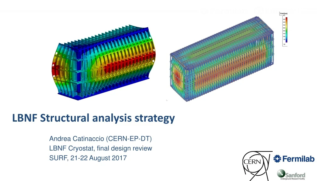
This document outlines the structural analysis strategy for the final design review of the LBNF Cryostat, covering analytical, FEA, and Eurocode3 verification methods with connections, membranes, and local reinforcements.

E N D
Andrea Catinaccio (CERN-EP-DT) LBNF Cryostat, final design review SURF, 21-22 August 2017 LBNF Structural analysis strategy
Outline • Introductionon models • Eurocode3 verification: Analytical - SCIAengineer – FEA • External consultant calculations on connections • FEA models for the reinforced membrane • Testing of main connections at Coimbra, Dept. of Civil Engineering
Calculation models implemented Several models have been implemented and results compared: • Analytical (EC3 code based) analyses of main structural elements and connections • SCIAengineer analyses (EC3 code based) with load combinations and imperfections • FEA models (beam, shell and solid element formulation) in order to: • Verify results obtained with SCIA global model • Detail study/analysis of critical areas of the LBNF cryostat • Beam Connections (welded and bolted) • Warm membrane and reinforcements • Floor reactions and support conditions • Local reinforcements (e.g. for access openings) Testing of most critical connections planned to validate FEA and Analytical models
Calculation models implemented The analyses have covered: • Load combinations and initial sway imperfections • Static and dynamic (seismic) stress-deflection behaviour • Global and local Stability • Evaluation against plastic collapse, by linear and non linear analyses (ANSYS, SCIAeng)
Loading and Materials New HL1110M*433 beams and news dimensions of portals • Static head of LAr: 14m (~100% filling ratio, ρ=1400kg/m3) • Top pressure: 130mbar to 350mbar (valve opening) • Weight of members: • Self-weight of composing members. Main beam members: HL1100M (433 kg/m) • Insulation plus inner corrugated membrane 105 kg/m2 (800 mm total thickness) • Stiffened warm membrane of 12 mm, 131 kg/m2 • Detector weight (dry) 200 tons distributed on the roof • Load cases with Seismic loads • Baseline Material: Grade S460ML (σy=440 MPa; UTS=540MPa) for main beams and membrane • Bolt grades 10.9 (preloading qualified bolts) Design Pressure Assumes uniform load transfer to warm membrane Loading corresponding to Unit Cell (pitch 1.6m)
2D and 3D Calculation models As presented at the end of 2016 2D Portal models Unit Cell (1.6m pitch) 3D models Length (outer) 65.84 m • This basic unit cell is the "portal". It takes the principal load - fluid pressure and weight • The standard cell is then completed by the longitudinal belts, to compose the main holding frame box • The warm membrane, reinforced with ribs, holds the pressure between the main beams, provide the tightness, and does not contribute to the strength of the main holding structure
Initial comparison portal beam vs SCIAeng • Results from the beam model for a direct comparison. • Calculations in EDMS doc. 1547687 (2nd assessment), with a load multiplier of 1.35 for permanent actions and hydrostatic pressure and of 1.4 for the design pressure of 350 mbar. Comparison with Ansys analysis EDMS doc. 1550696.HL1110M*433 beams Presented at Initial design review in 2015 Initial studies for thicker beam and nominal loads as benchmark Ref. documents: https://edms.cern.ch/document/1835609 Displacements: ANSYS run with EC3 load multipliers for comparison with EC3 calculations
Analytical and FEA models: ref. material Joao • EC3 SCIAengineer global models • Analytical calculations of members, connections, local openings • Seismic analysis
Calculations model: 3D beam (SCIAeng) • Covers full load combinations (example below out of 32 combinations by now): Shear Forces Moments Unity Check • SCIAengineer full verification according to Eurocode 3 (dedicated software). SCIAengineer envelope verification according to Eurocode 3 (main transversal portal). Envelope results used for Unity check verification and sizing of connections.
Calculations model: EC3 Analytical • Analytical calculations of openings Examples of results from analytical calculation of connections 25mm Example of main frame analytical end verification: Unity Check
Seismic Calculations : EC3 Analytical and FEM Hydrodynamic components: Rigid impulsive component (fraction of the fluid that moves together with the wall of the vessel) Convective pressure distribution corresponds to the distribution due to the sloshing of the fluid. Inertia effects: Additional uniformly distributed load on the structural elements. Total pressure distribution on the wall Example of input spectrum for FEA calculated from EDMS 1510132 examples of seismic analytical calculations
FEA ANSYS models: ref. material Diego • FEA global models: main holding structure with warm membrane • FEA local models: • Floor reactions and support conditions • Connections (welded and bolted) • Local reinforcements (e.g. for access holes)
FEASingle Portal Frame Model Eq. VM Stress (MPa) Corner Reaction Force ~1.4MN (Nominal loads) Very good agreement with ANSYS Global (shell) model and SCIA models Floor Analysis + BC input for beam connections’ sub-models
FEA global models Nominal Loads (po=350mbar, friction contact between primary structure and warm membrane - µ=0.05, rigid floor) ULS Loads (po=350mbar, friction contact between primary structure and warm membrane - µ=0.05, rigid floor) • Portal at the centre of the cryostat represents the worst case scenario
FEA global models: Main Structure and Warm membrane Nominal Loads (po=350mbar, friction contact between primary structure and warm membrane - µ=0.05, rigid floor)
FEA local models: Connections and Openings Reduced models & sub-modelling approach Top Connection Splice Connection • The local reinforcements help recovering part of the stiffness lost with the access openings Bottom Connection • Effects on the local instability is evaluated analytically (and in SCIA)
Joint Capacity - calculations by consultant Full report EDMS 1756431 on joint analysis available at: https://edms.cern.ch/document/1835609 Examples of specifications provided to the consultant for joint capacity calculations (8 main joints plus fin plate connection). Examples of analytical calculations done by the consultant on the joint capacity. Verified analytical by Joao, and by FEA by Diego and Luca
Local Analyses: ref. material Luca • EC3 and FEA analyses for • the reinforced membrane (main cryostat and door) • the membrane support brackets
Calculations models: Warm Membrane with ribs A Elastic Stress A Equivalent plastic strain < 0.8% Brackets VM stresses
Calculations models: Warm Membrane • Model: selection of 1/4th of the full cryostat membrane: • Assumption here: all forces from the short walls passing through the membrane (no contribution by the longitudinal belts). S FEd=3.6 MN FEd=9.2 MN FEd=6.7 MN Design Force acting on the membrane sections • Plate-to-plate butt weld sizing: • Full penetration weld: 17% utilisation factor; • 4 mm min required for full strength with partial penetration 4mm tm
Door opening - IPE reinforcement Rigid fin plate • Verified by EC3, by FEA and by Consultant. EDMS 1808385 https://edms.cern.ch/document/1808385
https://www.isise.net Full Scale Testing of Structural Connections • Collaboration withCoimbra Civil Engineering Test Lab • Tests will be carried out on full scale samples, max load at 125% of max envelope loads • 6 MN actuators procured Msd=4.2MN Vsd=2.65MN Msd=3.8MN Vsd=1.5MN C5- Slice C2- Top corner C6- Pinned connection C3- Splice Msd=8.4MN Vsd=2.65MN Images from Coimbra offer: red (concerns all test joints) and bleu components to be provided by CERN C0-web opening C1- Bottom corner (welded) C4- Splice
Documentation and References https://edms.cern.ch/document/1835609 • CEN, “NF EN 1991-1-1: Actions on structures — Part 1-1: General actions — Densities, self-weight, imposed loads for buildings,” 2003. • CEN, “NF EN 1990: Basis of structural design.” AFNOR, 2003. • CEN, “NF EN 1990/A1: Basis of structural design - Amendement A1 to NF EN 1990:2003.” AFNOR, 2006. • CEN, “NF EN 1990/A1/NA: Basis for design — National annex to NF EN 1990/A1:2006.” AFNOR, 2007. • EN 1993-1-1: Eurocode3 - General rules and rules for buildings. • EN 1993-1-5: Eurocode3 - General rules - Plated structural elements. • EN 1993-1-6: Eurocode3 - General rules - Strength and stability of shell structures. • EN 1993-1-7: Eurocode3 - General rules - Strength and stability of planar plated structures subject to out of plane loading. • EN 1993-1-8: Eurocode3 - Design of joints. • EN 1993-1-10: Eurocode3 - Material toughness and through-thickness properties. • EN 1993-4-2: Eurocode3 - Tanks • ANSI/AISC 360-10, Specification for Structural Steel Buildings. • Guide for Structural Steel Connections, Perry S. Green, Thomas Sputo, Patrick Veltri, AISC. • STEEL DESIGNERS' MANUAL - 6th Edition (2003), Bernard Godfrey. • Non Circular Pressure Vessels, British Engine Technical Report 1981, Volume XIV. • ANSYS APDL v15.0, ANSYS Structural Analysis Guide & Theory Reference Manual • ANSYS Workbench v15.0, User guide & Scripting Guide • SCIA Engineer 2015, Theory Steel Code Check • CATIA, Dassault Systems,V5 Version 5-6 Release 2013 SP5 User Manual • SMARTEAM Enovia, Dassault Systems, Editor V5-6R2013 SP3 User Manual
Summary • Optimisation of the load-carrying structure and Warm Membrane (4 assessments) • Selection of lighter standard beams. • Stronger longitudinal bracings • In depth verification of connections. • Stiffened membrane for easier assembly • Support conditions • Models developed for detailed analyses • Main portal (Beam models; Shell model; Solid Model) • Unit Cell (Beam Model; Beam + Shell Model) • Global Cryostat Model (Beam models; Beam + Shell Models) • Bolted & Welded Connections (Detailed solid Sub-models) • Reinforced Membrane (Global, sub-models) • Independent Eurocode 3, FEA and Consultant validation of the final design • Fully coherent results compliant with Eurocode 3 • Final further validation of critical connections planned by full scale testing and FEA correlation Analytical & Numerical (ANSYS, SCIA) Studies
List of symbols according to Eurocode 1990 and Eurocode 1993-1-9 Characteristic value of effect of actions Characteristic value of resistance Design value of effect of actions (Ek·gF) Design value of resistance (Rk/gM) Partial factor for actions, which takes account of the possibility of unfavourable deviations of the action values from the characteristic values. This factor accounts also for model uncertainties and dimensional variations Partial factor for a material property, also accounting for model uncertainty and dimensional variations Yield strength Ultimate strength Von Mises stress Deflection w Maximum allowable deflection wlim
Serviceability Limit State (SLS) verification: not applicable Example of verification: Ultimate Limit State (ULS) verification: for self weight, insulation, hydrostatic pressure for over-pressure 1.10 for section resistance (gM0) 1.25 for connection resistance (gM2) Example of verification: