Download
1 / 20
210 likes | 332 Vues
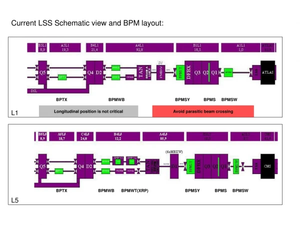
Schematic View of the MINOS Scintillator System. Scintillator Module. Extruded scintillator, 4.1 cm wide Two-ended WLS fiber readout. Strips assembled into 20 or 28-wide modules. WLS fibers routed to optical connectors. Light routed from modules to PMTs via clear fibers.

E N D
Schematic View of the MINOS Scintillator System Scintillator Module • Extruded scintillator, 4.1 cm wide • Two-ended WLS fiber • readout. • Strips assembled into • 20 or 28-wide modules. • WLS fibers routed to • optical connectors. • Light routed from modules • to PMTs via clear fibers. • 8 Fibers/PMT pixel in far • detector. (Fibers separated • by ~1m in a single plane.) • 1 Fiber/PMT pixel in near • detector (avoids overlaps). • Multi-pixel PMTs • Hamamatsu M16 (far), M64 (near) WLS Fibers WLS Fibers 8 m Optical Connector Optical Connector Clear Fiber Ribbon Cable (2-6 m) Clear Fiber Ribbon Cable (2-6 m) Optical Connector Optical Connector Connection to electronics Multiplex Box Multiplex Box Connection to electronics PMTs Objects not to scale
28 20 20 20 20 28 28 Far Detector Module Layout • 8 modules cover one far detector steel plane • Four 20-wide modules in middle (perp. ends) • Four 28-wide modules on edges (45 deg ends) • Two center modules have coil-hole cutout 28 Coil Bypass
Near Module Layout New Picture In Development Some changes under study.
Extruded Scintillator Light output measurements in Aug. 2000 Photo of a scintillator strip Typical light yield in Nov. 2000 Cross-section photo of two scintillator strips with fibers glued into grooves. As long as desired… Problems found and fixed! Rapid light output checks are important to establish and maintain high quality 10 mm 41 mm • Dow Styron 663 W polystyrene without additives • PPO and POPOP waveshifters (1% and 0.03% by weight) • 1.0 cm x 4.1 cm cross-section extrusion co-extruded with TiO2 reflector • Extruded groove for WLS fiber (which is glued into the strip) • Light output excellent for this collection geometry… better than • commercial cast scintillator machined to shape and wrapped with Tyvek.
WLS Fiber • Kuraray WLS fiber: • 1.20 +0.024 -0.005 mm diam. • 175 ppm Y11 fluor (K27) • polystyrene core, double clad (PMMA and polyfluor) • “Non-S Type” Light vs Position in WLS Fibers Attenuation curves for several fibers in the same batch from Kuraray (“batch” = 1000m) Typical “long attenuation” length ~6 m Light (arb. units) Fiber spool in use on the glue machine. Typical variation in light from far end is ~3%. Variation in light from the far end of 8 m fibers from one batch to another has a sigma of about 5%. Position (m)
Assembly Drawing for side-out snout manifold Top variable width seal Top Al cover Top Al light case Light Case Fiber routing manifold Manifold base with fiber grooves Connector Bottom Al light case Variable width seal Light injection cover Bottom Al Cover Formed Al cover Light injection manifold Bottom variable width seal Module Components • The scintillator modules are a laminate of scintillator strips (with WLS fiber glued into the groove) with aluminum skins. • WLS fibers are routed through end manifolds to bulk optical connectors. • The entire assembly is light-tight. Optical connector Module parts for “straight-out” manifold
Typical response for a 3.5 m long cable compared to a reference 1m cable with ~90% absolute transmission. Typical attenuation length ~ 14m! Clear Fiber Coiled conduit with fibers (loose) inside. shroud shroud connectors Photo of a complete cable Schematic of a Cable 20/28 Fibers per cable 1.2 mm diam. Kuraray double clad fiber Clear fiber cables transmit light from modules to PMT boxes
PMTs • Hamamatsu R5900 series multi-anode PMTs have been selected: • 16 pixel tubes for the far detector (pixel size 4mm x 4mm) • 64 pixel tubes for the near detector (pixel size 2mm x 2mm) • Gain of 106 consistent to x2 (M16) or x3(M64) • QE at 520 nm typically 13.5% • Good single pe peak • Very fast signals and low time jitter. Fiber Layout 16 mm Cut-away view of R5900 series PMT M16 M64
PMT Boxes and Connectors Cookie with fibers PMT Mounting Components • Far detector (shown) • 3 M16 PMTs/box • 8 fibers per pixel “optical multiplexing” • Each box serves 2 planes (one side) Alignment window (not installed) Adjustable mounting bracket (alignment) PMT jacket M16 PMT Spring loaded PMT base Front-end electronics Connector pair
Light Injection System • The light injection system provides short term PMT gain checks, linearity checks and monitoring of light transmission. • 16 pulser boxes, 20 LEDs per box • Light from each LED fanned out x 50 • Light distribution uniform to within a factor of 2 • Up to 150 pe’s observed at PMT channels • 12 bit resolution on amplitude control Light Injection Prototype PIN Diodes Light fanout cone Acrylic fibers to distribute LED light Module End Manifold Light fanout cone WLS Fibers LED Pulse Boxes Light Injection Pockets Schematic of Light Injection System Relative light in fibers
Calibration Detector • The calibration detector is a small version of the “big detectors” to be exposed in test beams: • 1 m square x 60 planes deep • All technology as in MINOS near and far detectors (both technologies where there are differences.) • Provide hadronic energy scale • Detailed topology studies • Calibration transported between detectors using cosmic ray muons Waiting for drawing of detector.
Automated Production Equipment Automatic Fiber Gluing Machine: Lays down bead of glue, unrolls fiber from spool, pushes fiber into glue in groove and covers the groove with a reflector. Automated Module Mapper with 28 strip-wide module (8m x 1.2 m). Uses computer driven x-y scanning table with 137Cs source. Computer control and readout Fiber spool Glue dispenser x-y bridge Gluing apparatus source Module 28 strip-wide module Light injection manifold Optical connector PMT Box Fibers at connector Clear fiber cable
Light Case assembly/forming Fiber Gluing Machine Racks filled with modules The “Gluing Room” Overview of section of a factory Mapper DAQ Mapper with short 45 Crimping/detailing table with long45 and lifting fixture Module storage rack with 5 full assembly trays Scintillator strip crates Module Factories Module on shuttle table Module with fibers glued in.
System Light Output Number of observed photoelectrons Number of observed photoelectrons A typical 45o module One of the best modules Note: The drop in light at the two ends is due to different lengths of strips at the ends. Distance along the module (m) Distance along the module (m) Light output vs position of cosmic ray muons passing nearly perpendicularly through a scintillator module averaged over all strips within a module. The light output is measured using the full MINOS readout apparatus (connectors, clear fibers, PMTs…). The light read from each end of a module is shown along with the sum of light from each end.
4PP Operations Clear Fiber Cables MUX Box Trigger module Module Manifolds Trigger module Connectors Steel Octagon Rabbit Crate “Downstream View” “Edge View” Cosmic ray muons are readout using an external trigger in the 4 Plane prototype (3 scintillator planes). Results are consistent with previous cosmic ray tests made one year earlier with the modules horizontal in the cosmic ray test stand.
Cosmic Ray Muons in the 4PP Typical single photoelectron spectrum from light injection Number of observed photoelectrons per muon (corrected to 1 cm thickness) pedestal single pe peak Note: The data are from a small section of the 4PP where the trigger counters cover. Used to determine PMT gains
Some Scintillator System Parameters • Some major system features • Extruded Polystyrene Scintillator: 300 T, 600 km of 4.1x1.0 cm2 strips. • WLS Fiber: Kuraray double-clad 1.2 mm diam., 175 ppm Y11, 780 km • Scintillator Modules: 20/28 strips wide and up to 8m long. ~4300 mods., ~28,000 m2 • Clear Fiber: Like WLS, no fluor, 1100 km of fiber built into cables with 20/28 fibers. • PMTs: • Far detector: Hamamatsu M16 with 8 fibers per pixel with fibers readout from each side of the detector. 3 tubes per plane, ~1500 tubes • Near detector: Hamamatsu M64 with one fiber per pixel and fibers readout from one side of the detector (with reflectors on the far end). ~200 tubes. • Light Injection: Blue LED illumination of all WLS fibers to rapidly track PMT response. • Performance Requirements: • Light output: > 4.7 observed pe’s on average for a MIP crossing. • Time measurement: s < 5 ns per plane for MIP crossing. • Calibration: • Relative near/far energy response to within 2%. • Absolute hadronic energy response to within 5%.


![Schematic view of particle production in the atmosphere [8]](https://cdn3.slideserve.com/6902772/slide1-dt.jpg)