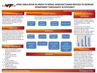
Objective
Learn about pumps: what they are, how they work, and their various applications in industries. Explore centrifugal, reciprocating, and rotary pumps, including operating principles and classifications. Gain insights on pump cavitation.

Objective
E N D
Presentation Transcript
Objective • At the end of this session you will able to describe • What is pump • Application of pump • Classification of pump • Centrifugal pump • Reciprocating pump • Rotary pump • Pump cavitation
What is Pump? • A pump is a mechanism that is used to transfer a liquid from one place to another by imparting energy to the liquid being transferred. • The Hydraulic machines which convert the mechanical energy into hydraulic energy are called pumps. The hydraulic energy is in the form of pressure energy.
Application of Pump • Pumps are employed to move materials ranging from molten metals at very high temperatures, to cryogenic materials at extremely low temperatures. They are used to generate pressures so small as to be barely perceptible, to pressures so high that the liquid being pumped is capable of cutting through material as though it were a saw. Also. they are designed to supply quantities from as small as one drop per day, to four billion liters per day. They have power requirements from a few watts to nearly 75 megawatts.
Application of Pump Some of the more common types of pumps required in industrial plants are: • Boiler feedwater pump - supplies the boiler with feedwater as required. It must be capable of forcing this water into the boiler against the pressure existing in the boiler. • Fuel oil pump - used in oil-fired boilers to pump fuel oil to the burners. • Lubricating oil pump - used to circulate oil to the bearings of a machine such as a turbine, engine, pump or compressor. • Circulating water pump - also called a cooling water pump. It is used to pump water through a heat exchanger such as a condenser or an oil cooler. • Chemical feed pump - small capacity units are used to pump chemicals into boilers: larger units are used as process pumps. • Fire pump - used to supply water to plant fire lines. • Domestic water pump - used to supply water to plant washrooms, etc.
Classification of Pump Pumps fall into two main categories: • Those that use liquid velocity to create pressure. • Those that use positive displacement to create pressure. Pumps are classified, according to their method of operation, as: • Reciprocating Pump • Centrifugal Pump • Rotary Pump
Centrifugal Pump • A centrifugal pump may be defined as a pump that uses centrifugal force to develop velocity in the liquid being handled. The velocity is then converted to pressure when the liquid velocity decreases. As kinetic energy is decreased, pressure is increased
Centrifugal Pump OPERATING PRINCIPLE • The working principle of a centrifugal pump is shown diagrammatically in Figure 1. Rotation of the impeller causes any liquid contained in it to flow towards the periphery because of the centrifugal force generated. The center or eye of the impeller is thus evacuated and liquid from the suction line then flows in to fill the void.
Centrifugal Pump Centrifugal pumps can be subdivided into the following types: • volute, • diffuser, • axial flow, • mixed flow • regenerative.
Volute Centrifugal Pump • Basically, the volute centrifugal pump consists of an impeller, made up of a number of vanes, which rotates in a volute stationary casing. The term "volute" refers to the gradually increasing cross-sectional area of the spiral casing.
Volute Centrifugal Pump • The liquid being pumped is drawn into the center or eye of the impeller. It is picked up by the vanes, accelerated to a high velocity and discharged into the casing by centrifugal force. As the liquid travels through the volute casing to the discharge, its velocity energy is converted into pressure energy. Since the liquid between the vanes is forced outward, a low pressure area is created in the eye and more liquid is drawn in through the suction inlet. As a result, the flow of liquid through the pump is constant
Diffuser Pump • In the diffuser centrifugal pump, the high velocity liquid leaving the impeller passes between a number of vanes in a stationary diffuser ring. These vanes are shaped in such a way that the channels between them gradually increase in area. As the liquid passes through these channels, its velocity energy is converted into pressure energy. The liquid is then discharged either into a volute casing or into a concentric casing where farther velocity to pressure conversion takes place.
Diffuser Pump • As these diffuser vanes are spaced uniformly around the impeller circumference there is no radial imbalance developed. In addition, in the diffuser pump the velocity energy of the liquid is more completely converted into pressure energy than it is in the volute pump. As a result, the diffuser pump is commonly used for high capacity, high pressure service.
Axial Flow Pump • Axial flow pumps, also referred to as propeller pumps, use impellers with blades similar to those of an aircraft propeller. The pump head is developed by the propelling or lifting action of the blades on the liquid. • The arrangement of the pump is usually vertical as in Figure but horizontal and inclined shaft arrangements are also available. For the smaller pumps, fixed blade type impellers are used. Larger pumps may use impellers with adjustable or variable-pitch blades which can be used to maintain efficiency at loads that differ from the design load.
Impeller Types • Impellers vary considerably in design. They can be classified according to specific speed, the way the liquid is drawn into the eye, vane design and pump application
Impeller Types • The open impeller, A, has vanes attached to a central hub with a relatively small shroud on one side. It is of end suction or single-inlet design, thus the water enters the eye from one side only. B shows a semi closed single-inlet impeller. A full shroud closes off one side. An enclosed, single-inlet impeller is shown in C. The liquid passages between the vanes are closed off by the shrouds on both sides. Impeller D is also enclosed but it has a double-inlet, thus water enters the eye from both sides. Design E is used in paper-stock pumps handling liquids containing solids. F is a propeller type impeller while impeller G is used in mixed-flow pumps.
Multistaging • Pumps may be either single or multistage design. In-general, single stage pumps are used for heads of 120 m or less while the multistage design is usually necessary for heads above 120 m. To obtain these higher heads, centrifugal pumps are equipped with two or more impellers operating in series. That is, the discharge of one impeller is connected to the suction of the next impeller. These pumps are known as multistage pumps.
Axial Flow Pump • The advantages of axial flow pumps are their compact size and the ability to operate at high speeds, while their disadvantages include low suction lift capacity and relatively low discharge bead capability. They are used mainly for low head, high capacity applications and are available in the singlestage design or the multistage
Mixed Flow Pumps • Mixed flow pumps combine some of the characteristics of the volute and diffuser pumps together with some axial flow pump features. The head developed by this pump is produced partly by centrifugal force and partly by the lift of the impeller vanes on the liquid. • The mixed flow pump shown in Figure has a single-inlet impeller. The flow enters the pump in an axial direction and leaves the pump in a direction somewhere between axial and radial.
Mixed Flow Pumps • The mixed flow pump, combines some of the characteristics of the radial flow and axial flow pumps. It develops its discharge head by using both centrifugal force and lift of the vanes on the liquid. The pump is built for vertical and horizontal applications and it is commonly used for low head, high capacity operation.
Regenerative or Turbine Pump • The regenerative pump or turbine regenerative pump as it is also called, features an impeller with a double row of vanes cut in the rim, as illustrated in Figure 22. Both the suction and the discharge connections are located in the casing at the periphery of the impeller. The liquid circulates almost 360 degrees before being discharged
NPSH • The NPSH required by a pump is the head of the liquid pumped, measured at the suction nozzle of the pump, necessary to overcome all energy requirements at the inlet of the pump (these included friction losses, acceleration, heating effect of internally circulated liquid etc.) and thereby avoid any vaporization of liquid in the pump suction. The NPSH required is thus the head of the liquid required at the pump suction nozzle above the vapour pressure of the liquid at that point. • for centrifugal pump The NPSH required is expressed in terms of head of liquid pumped, andnot pressurewhile for positive displacement pump NPSH are not always expressed in terms of head of liquid. In some cases-as in the case of Reciprocation Pumps- NPSH is expressedas a pressure increment above the vapour pressure of the liquid
NPSH • NPSHA (Available) = Terminal Pressure in the vessel (in gauge)(+) Static Head of fluid above pump centre line .(+) Atmospheric Pressure(-) Vapour Pressure of liquid at pumping temperature(-) Friction loss in suction piping up to pump centre line consisting of the following • NPSHR (required): The net positive suction head required is a function of the pump designat the operating point on the pump performance curve • At any fixed speed, the NPSH required by a centrifugal pump will increase with increase in flow from rated flow. At substantially increased flow from design flow the increase in NPSHR is very rapid
ADVANTAGES AND DISADVANTAGES OFCENTRIFUGAL PUMPS • The advantages of centrifugal pumps include simplicity, compactness, weight saving, and adaptability to high-speed prime movers. One disadvantage of centrifugal pumps is their relatively poor suction power. When the pump end is dry, the rotation of the impeller, even at high speeds, is simply not sufficient to lift liquid into the pump; therefore, the pump must be primed before pumping can begin. For this reason, the suction lines and inlets of most centrifugal pumps are placed below the source level of the liquid pumped. The pump can then be primed by merely opening the suction stop valve and allowing the force of gravity to fill the pump with liquid. The static pressure of the liquid above the pump also adds to the suction pressure developed by the pump while it is in operation. Another dis- advantage of centrifugal pumps is that they develop CAVITATION. Cavitation occurs when the velocity
Cavitation • Cavitation is defined as phenomenon of formation of vapour bubbles of a flowing liquid in a region where the pressure of the liquid falls below its vapour pressure and collapsing of these vapour bubbles in a region of higher pressure. When the vapour bubbles collapse and very high pressure is created, the metallic surface above which the liquid is flowing is subjected to these high pressures which cause pitting action on the surface, thus cavities are formed on metallic surface and also considerable nose and vibration created. • formation of vapour bubbles of flowing liquid takes place only whenever the pressure in any region falls bellow vapour pressure, at this time liquid starts boiling and vapour bubbles forms, these bubbles carried along with the flowing liquid to the higher pressure zone where this bubbles condense and bubbles collapse due to sudden collapsing og the bubbles on metallic surface high pressure is produced and surface subjected to high local stress.
Cavitation • Precaution against cavitation • The pressure of the flowing liquid in any part of the hydraulic system should not be allowed to fall below vapour pressure ( NPSHA>NPSHR). • The special material or coating such as aluminum bronze and stainless steel should be used.
Positive Displacement Pump • By definition, positive-displacement (PD) pumps displace a known quantity of liquid with each revolution of the pumping elements. This is done by trapping liquid between the pumping elements and a stationary casing. Pumping element designs include gears, lobes, rotary pistons, vanes, and screws. • PD pumps are found in a wide range of applications -- chemical-processing; liquid delivery; marine; biotechnology; pharmaceutical; as well as food, dairy, and beverage processing. Their versatility and popularity is due in part to their relatively compact design, high-viscosity performance, continuous flow regardless of differential pressure, and ability to handle high differential pressure.
RECIPROCATING PUMP • In a reciprocating pump, the pumping action is produced by the to and fro (reciprocating) motion of a piston or plunger within a cylinder or by the flexing action of a diaphragm. • Piston pumps may be either single-acting or double-acting. A single-acting pump will deliver liquid when the piston moves in one direction only and a double-acting pump when the piston moves in either direction. Plunger and diaphragm pumps are usually single-acting. • Reciprocating pumps are referred to as simplex pumps when they have one piston or plunger, duplex when they have two pistons, triplex when they have three pistons, etc.
RECIPROCATING PUMP • In one revolution of the crankshaft, a single-acting simplex pump will deliver one pulse of liquid. A triplex double-acting pump will deliver six pulses of liquid in one crankshaft revolution. The crankshaft throws (eccentrics) on a triplex pump are set 120º apart. When one stroke takes 180º to complete, it must follow that when one piston is nearing the end of its delivery stroke, another piston is just beginning its delivery. The advantage of this type of pump is that it not only increases the volume of output, but it also reduces the surging and vibration caused by intermittent flow in a simplex pump. Some high-pressure pumps further reduce the surging by installation of a surge accumulator on the pump discharge line. • Surge accumulators may be referred to as "bumpers" or air chambers, as they may be filled with air. Some are designed with a diaphragm to separate the chamber from the liquid being pumped. This cushion above the diaphragm may be filled with air or nitrogen. • Reciprocating pumps can be divided into two classes according to the pump drive: • Direct-acting in which the the piston rod of the driver is connected directly to the piston rod of the pump. In a direct-acting, steam-driven pump, the movement of the piston in the water cylinder is produced by a steam piston in a steam cylinder. • Power-driven in which a crankshaft is driven by a separate power source, such as an electric motor.
SINGLE-ACTING PUMPS • Referring to Fig. when the plunger moves from right to left, the pressure in the cylinder drops below the pressure in the suction line and liquid is drawn into the cylinder through the suction ball check. The high pressure in the discharge line keeps the discharge ball check firmly on its seat. At the end of its travel, the plunger reverses direction and starts moving from left to right. This raises the pressure in the cylinder above the pressure in the discharge line and the liquid is forced out via the discharge ball check. The suction ball check is forced shut while the discharge valve is forced open by the pressure of the liquid. Liquid is discharged only when the plunger is moving from left to right, hence the name single-acting. The movement of the plunger in one direction is called the stroke of the plunger. The distance the plunger moves in and out of the cylinder is the length of stroke
DOUBLE-ACTING PUMPS • The double-acting pump in Figure 4 has two discharge valves, D.A. and D.B.and two suction valves, S.A. and S.B. When the piston moves from left to right as shown in Fig. a), the liquid will be drawn in through suction valve S.A. while at the same time liquid, on the other side of the piston, is being forced out through the discharge valve D.B. When the piston reverses and moves from right to left as in Fig. b liquid is drawn in through the suction valve S.B. and at the same time liquid is forced out through the discharge valve D.A. With this arrangement, liquid is discharged when the piston moves in either direction, hence the name double-acting
DIAPHRAGM PUMPS • The diaphragm pump differs from the piston or plunger-type reciprocating pump in that the fluid being pumped is completely isolated from the reciprocating mechanism by a diaphragm, thereby eliminating leakage along the piston rod and plunger. • The diaphragm is a flexible membrane which acts as the liquid displacement component. The diaphragm can be made of flexible metal or nonmetallic materials such as plastic, rubberor neoprene, depending on the fluid being pumped.
DIAPHRAGM PUMPS • A cross-sectional view of a mechanically actuated diaphragm pump is shown in Figure. The diaphragm, D, is attached to the piston guide, P, by the disc, B. An eccentric is used to produce the reciprocating motion of the guide, P, causing the diaphragm to move to and fro, resulting in pumping action.
ROTARY PUMP • Rotary pumps are positive displacement pumps. Instead of imparting high velocity to the liquid due to centrifugal force, as in a centrifugal pump, rotary pumps trap the liquid between a close fitting casing and either gears, lobes, vanes or screws. The liquid is pushed from the suction to the discharge of the pump. Unlike reciprocating pumps, the flow of liquid through rotary pumps is continuous and the discharge is smooth, without pressure fluctuations. • Gear pump (external, internal gear), lobe pump (two lobe three lobe), vane pump( sliding, flexible vane) screw pump, progressive cavity pump are examples of rotary pump
External Gear Pump • The most common rotary pump is probably the external gear pump, also known as the gear pump or the spur gear pump. • The external gear pump shown in Fig. consists of a housing containing two gears; the driving gear at the top and an idler or driven gear at the bottom. As the gears rotate, the liquid fills the voids between the gear teeth. The rotation carries these voids or pockets to the discharge side of the pump where the teeth of opposite gears mesh, filling the pockets and displacing the liquid carried in them. For this reason, the gear pump is called a positive displacement pump, as the gear tooth and the liquid cannot exist in the same pocket at the same time. The empty pocket continues its rotation to the suction side of the pump and as the teeth disengage, the void created is filled with liquid from the suction line. The small clearance between the gears and the pump casing minimizes the amount of leakage from the discharge side to the suction side.
External Gear Pump • The rotation and flow arrows indicate the path of the liquid. A common misconception is that the liquid is somehow squeezed through the teeth to produce pumping action. • The top or driving gear is keyed to the shaft which may be driven directly by a motor or indirectly by means of belts or gears. • If the clearance at the ends of the gears and between the gears and the casing, is small and the suction lift is not too great, a gear pump can prime itself by discharging the air trapped in the casing.
External Gear Pump • Advantages • High speed. • Medium pressure. • No overhung bearing loads. • Relatively quiet operation. • Design accommodates wide variety of materials. • Disadvantages • Four bushings in liquid area. • No solids allowed. • Fixed End Clearances.
Applications • Industrial and mobile applications • Fuel and lubrication • Metering • Mixing and blending (double pump) • Hydraulic applications • OEM configurations • Precise metering applications • Low-volume transfers • Light or medium duty
INTERNAL GEAR PUMP • The internal gear pump has an externally-cut gear which meshes with an internally-cut gear on one side of the casing. The internal gear is separated from the external gear on the opposite side by a crescent-shaped partition which prevents liquid from passing back from the discharge to the suction side. Liquid from the suction side fills the spaces between the teeth of both gears when they un mesh and is forced out of these spaces into the discharge when the gears mesh again.
Internal Gear Pumps Advantages • Two moving parts • One stuffing box • Positive suction, no pulsating discharge • Ideal for high viscosity liquids • Constant and even discharge regardless of varying pressure conditions • Low NPSH required • Easy to maintain • Disadvantages • Low speeds usually required • Medium pressure • One bearing runs in pumped product • Overhung load on shaft bearing
Applications • Barge, tanker, and terminal loading and unloading. • Filtering. • Circulating. • Transferring. • Lubricating. • Booster. • General industrial. • Marine applications. • Petrochemical. • Light, medium, or heavy-duty service
LOBE PUMP • The lobe pump (three lobe pump) in Figure has similarities to the external gear pump. Liquid is pushed from the suction side of the pump to the discharge side in a similar path to that of the gear pump. The pockets are larger and the quantity of liquid handled is greater (up to 12 000 liters/min), but the head is reduced to a maximum of about 750 kPa. The gear pump has a driver and an idler gear. This is not possible in the lobe pump as the drive lobe might slip out of synchronization with the idler lobe when working against a head pressure. External synchronizing gears drive the lobes to avoid this problem.
LOBE PUMP • Clearances in positive displacement pumps have to be kept to a minimum. Some lobe pumps have wear strips on the tips of the lobes, which can be renewed when wear occurs. • Lobe pumps and gear pumps are usually unsuitable for pumping liquids containing abrasives as wear would reduce their efficiency. A two lobe pump is illustrated in Figure
LOBE PUMP • Advantages • Pass medium solids. • No metal-to-metal contact. • Superior CIP/SIP capabilities. • Positive suction, non pulsating discharge. • Disadvantages • Requires timing gears. • Requires two seals. • Reduced lift with thin liquids.
Applications • Food processing. • Beverages. • Dairy Produce. • Personal Hygiene Products. • Pharmaceutical. • Biotechnology. • Chemical. • Industrial. • Medium and heavy duty cycles
SLIDING VANE PUMP • The sliding vane pump has a rotor with slots spaced evenly around it. Vanes in these slots are free to slide in and out to meet the casing wall. The rotor is eccentrically mounted in the pump cavity with only enough clearance to avoid contact with the casing at the closest point. The vanes are forced out against the casing wall by centrifugal force and the liquid trapped between the vanes is carried around from suction to discharge. As the vanes pass the suction port they are rotating into an increasing void. Liquid from the suction line fills the void. As the vanes continue to rotate they pass the point of maximum clearance between the rotor and housing and the void then begins to diminish. As the volume decreases, the trapped liquid is forced out the discharge side of the pump.
SLIDING VANE PUMP • Advantages • Medium capacity • Medium speed • Thin liquids • Sometimes preferred for solvents, LPG • Can run dry for short periods • Can have one seal or stuffing box • Develops good vacuum • Disadvantages • Can have two stuffing boxes • Complex housing • Not suitable for high pressures • Not suitable for high viscosity • Not good with abrasives
SCREW PUMPS • The screw pump in Fig. features a power rotor situated between two idler rotors. The liquid is drawn into both ends of the rotor where it is trapped in the pockets formed by the threads. The liquid is carried between the screw threads along the axes of the screws as in a screw conveyor. The liquid is discharged at the middle of the rotors. • The idler rotors are driven by liquid pressure and there is no metal to metal contact between idlers and power rotor. This design may operate at pressures up to 7000 kPa and at speeds up to 7000 r/min.
SCREW PUMPS • A variation of the screw pump is the two rotor screw pump shown in Fig. This pump has two rotors, each with opposing helical threads. The liquid is trapped between the screw threads and the pump casing and is conveyed axially by the meshing of the rotors, until it is discharged in the middle. The two rotor screw pump uses timing gears to keep the rotors synchronized
Advantage of Screw pump • Wide range of flows and pressures • Wide range of liquids and viscosities • Built-in variable capacity • High speed capability allowing freedom of driver selection • Low internal velocities • Self-priming with good suction characteristics • High tolerance for entrained air and other gases • Minimum churning or foaming • Low mechanical vibration, pulsation-free flow, and quiet operation • Rugged, compact design -- easy to install and maintain • High tolerance to contamination in comparison with other rotary pumps (Fraser, et. al., 1986)