Dimensioning and Sizing Standards in Drafting: Line Types, Dimensioning Techniques, and Tolerancing
Learn about standards for sizing drawings in drafting, importance of line types, various dimensioning techniques, and tolerance guidelines. Discover how to apply proper line thickness, styles, and precedence of lines, and how to dimension objects effectively.


Dimensioning and Sizing Standards in Drafting: Line Types, Dimensioning Techniques, and Tolerancing
E N D
Presentation Transcript
DIMENSIONING Sizing of drawings in Drafting has standards and guidelines.
Lines on an engineering drawing signify more than just the geometry of the object and it is important that the appropriate line type is used. Line Thickness For most engineering drawings you will require two thickness', a thick and thin line. The general recommendation are that thick lines are twice as thick as thin lines. Line Styles Other line styles used to clarify important features on drawings are:
0.6 mm 0.3 mm 0.6 mm Precedence of Lines • Visible linestakes precedence over all other lines • Hidden linesand cutting plane lines take precedence over center lines • Center lineshave lowest precedence
For Example: 1. Visible 2. Hidden 3. Center
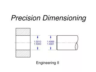
Dimensioning A dimensioned drawing should provide all the information necessary for a finished product or part to be manufactured. An example dimension is shown below. Dimensions are always drawn using continuous thin lines. Two projection lines indicate where the dimension starts and finishes. Projection lines do not touch the object and are drawn perpendicular to the element you are dimensioning. All dimensions less than 1 should have a leading zero. i.e. .35 should be written as 0.35
Types of Dimensioning • Parallel Dimensioning • Parallel dimensioning consists of several dimensions originating from one projection line.
Superimposed Running Dimensions • Superimposed running dimensioning simplifies parallel dimensions in order to reduce the space used on a drawing. The common origin for the dimension lines is indicated by a small circle at the intersection of the first dimension and the projection line.
Chain Dimensioning • Combined Dimensions • A combined dimension uses both chain and parallel dimensioning.
Dimensioning of circles • (a) shows two common methods of dimensioning a circle. One method dimensions the circle between two lines projected from two diametrically opposite points. The second method dimensions the circle internally. • (b) is used when the circle is too small for the dimension to be easily read if it was placed inside the circle.
Dimensioning Radii • All radial dimensions are proceeded by the capital R. • shows a radius dimensioned with the centre of the radius located on the drawing. • (b) shows how to dimension radii which do not need their centres locating.
Tolerancing • It is not possible in practice to manufacture products to the exact figures displayed on an engineering drawing. The accuracy depends largely on the manufacturing process. A tolerance value shows the manufacturing department the maximum permissible variation from the dimension. • Each dimension on a drawing must include a tolerance value. This can appear either as: • a general tolerance value applicable to several dimensions. i.e. a note specifying that the General Tolerance +/- 0.5 mm. • or a tolerance specific to that dimension
1. Dimensions should NOT be duplicated, or the same information given in two different ways. Incorrect
1. Dimensions should NOT be duplicated, or the same information given in two different ways.
2. No unnecessary dimensions should be used – only those needed to produce or inspect the part. Incorrect
2. No unnecessary dimensions should be used – only those needed to produce or inspect the part.
3. Dimensions should be attached to the view that best shows the contour of the feature to be dimensioned. Incorrect
3. Dimensions should be attached to the view that best shows the contour of the feature to be dimensioned.
4. Whenever possible, avoid dimensioning to hidden lines and features. Incorrect
4. Whenever possible, avoid dimensioning to hidden lines and features.
6. A dimension should be attached to only one view; for example, extension lines should not connect two views. Incorrect
6. A dimension should be attached to only one view; for example, extension lines should not connect two views.
7. Whenever possible, locate dimensions between adjacent views. Incorrect
7. Whenever possible, locate dimensions between adjacent views.
Multiple extension line crossings may be confused for the outside corner of the part. 8. Avoid crossing extension lines, but do not break them when they do cross.
9. Whenever possible, avoid sending extension lines through object views. Incorrect
9. Whenever possible, avoid sending extension lines through object views.
10. In general, a circle is dimensioned by its diameter and an arc by its radius.
11. Holes are located by their centerlines, which may be extended and used as extension lines.
12. Holes should be located and sized in the view that shows the feature as a circle. Incorrect
12. Holes should be located and sized in the view that shows the feature as a circle.
13. Do not cross a dimension line with an extension line, and avoid crossing dimensions with leader lines.
13. Do not cross a dimension line with an extension line, and avoid crossing dimensions with leader lines.
14. Leader lines point toward the center of the feature, and should not occur horizontally or vertically.
Incorrect 15. Dimension numbers should be centered between arrowheads, except when using stacked dimensions, and then the numbers should be staggered.
15. Dimension numbers should be centered between arrowheads, except when using stacked dimensions, and then the numbers should be staggered.
16. Concentric circles are dimensioned in the longitudinal view, whenever practical. Incorrect
16. Concentric circles are dimensioned in the longitudinal view, whenever practical.
Drawing layout All engineering drawings should feature a title block. The title block should include: Title:- title of the drawing Name:- name of the person who produced the drawing Checked:- before manufacture, drawings are usually checked Version:- many drawings are amended, each revision must be noted Date:- the date the drawing was produced or last amended Notes:- any note relevant to the drawing Scale:- the scale of the drawing Company name:- name of the company Projection:- the projection system used to create the drawing