Download
1 / 29
290 likes | 414 Vues
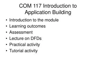
COM 117 Introduction to Application Building. Introduction to the module Learning outcomes Assessment Lecture on DFDs Practical activity Tutorial activity. Assessment Strategy. Group project 60%. Assessment Strategy TCT on design techniques (multiple choice and short answer) 20%

E N D
COM 117 Introduction to Application Building • Introduction to the module • Learning outcomes • Assessment • Lecture on DFDs • Practical activity • Tutorial activity
Assessment Strategy Group project 60% • Assessment Strategy • TCT on design techniques (multiple choice and short answer) 20% • TCT lab test on further Access Database Skills 20% • Group project 60% • Good interface (Input/output design) 10% • Modelled requirements’ documentation 20% • Level of complexity and accuracy in application 30% • Ease of use of system 10% • Choice of sample data 10% • Reports 10% • Testing documentation 10%
Timetable • http://osiris.sunderland.ac.uk/~cs0lhu/Lynne/com117.htm
Introduction SSADM What is a Data Flow Diagram? Why do we use DFDs? Levelling Conventions Decomposition and Abstraction The Elements Process and Data Stores External Entity DataFlow The Levels Rules
Constructing DFDs The Document Flow Diagram The Context Diagram Draw the external entities and data stores Level 1 Physical DFD Example: Hairdressing Salon Level 1 Physical DFD Summary
S.S.A.D.M. • S.S.A.D.M. - Structured Systems Analysis and Design Method • Uses different techniques to model a system • Data Flow Diagrams • Entity Relational Model (Logical Data Stores) • Normalisation
What is a Data Flow Diagram? • Known as DFDs • A way to model a real world situation • They model the real world situation which aids discussion and clarity amongst users, analysts and designers.
Why do we use DFDs? • It is a way of taking the physical view and converting it into a logical view. • The physical view - all documents involved • The logical view - the data they contain • Their main purpose is to communicate with the user, the analyst’s understanding of the scope of the required system
Levelling • Levels determine the amount of information shown • Context diagrams show environment • Each level shows more info. than the last • DFDs are expanded or decomposed into levels. • Separating each process into sub processes • Uncovers more and more detail
Conventions Balancing Process at lower level should have identical data flows if they flow out of a process Modelling Data Stores Only use DATA STORES used within this process on the diagram Numbering 1 - 1.1 - 1.1.1 1.2 - 1.2.1 Labels Should carry as much meaning as possible
Decomposition and Abstraction • Decomposition - Divide and subdivide into manageable size problems • Abstraction - Concentrate on the important issues and ignore the irrelevant
The Elements The four main elements of DFDs notation • Data Flows, with a label to indicate what data is flowing • Processes, that handle the data • Data stores, within the system (diary, filing cabinet or computer file) • External entities, outside sources of data
Process and Data Stores A process is made up of Data Stores Destination (Place or Name) Process Number Process description Should be descriptive, starting with a verb. Can be M for manual or D for computer base data stores. Name of Store M1
External Entity Is anything outside the system that is of interest to the system. Can be a person, a company or another system. Customer a Outside entity shows the Name and a lowercase alpha character is used to uniquely identify it. Customer a If an outside entity is repeated for the purpose of neat layout a line is added across the top.
DataFlow Is shown by a line with an arrowhead, indicating the direction of the flow of data. Each data flow should be named to indicate what data is being passed. Nouns or adjectives only no verbs are permitted.
The Levels • Context - Overview - contains only one process • Level 1 - Utilises all four elements • Level 2 - A breakdown of a level 1 process • Level 3 - A breakdown of a level 2 process • There is no rule as to how many levels of DFD that can be used.
Rules Sequence not important - getting the Process correct is • Context or Level 0 - Identifies the system/ boundary/External Links • Level 1 - Overview of function • Level 2 - Breakdown to Understand Hard to know where to stop Rule of Thumb If there are more than 8 data flows break it Process of Identifying major Processes
Process 3 Level 2 3 Hair/Reception Client a Clie a 3.1 Hairdresser Appointment Details Conduct Appointment Hair Details M2 Diary 3.2 Hairdresser Inform Reception Change of Hair Details 3.3 Receptionist Complete Appointment M3 Client Card
What happens if part of the system is on computer? • Electronic datastores • The above example was based on a manual system. If the datastores are computer records rather than manual files the convention is to label the datastore D1, D2 etc. D1
Summary SSADM What a DFD is & Why we use them The conventions What the elements are