Download
1 / 14
140 likes | 156 Vues
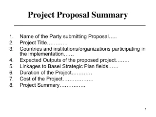
This proposal outlines the target test plan for TT2A, including power supply options, cryogenics solution, preliminary equipment proposal, and pulse list parameters. It also highlights the required manpower and jet chamber designs for the study.

E N D
Summaryfor proposal of TT2A target test H.Kirk, A.Fabich March 2004 week 9 http://proj-hiptarget.web.cern.ch A.Fabich, H.Kirk
Webpage for minutes/Credits C.Martins AB/PO M.Giovannozzi, C.Carli, S.Hancock AB/ABP-RF F.Haug, AT/ECR A.Fabich, H.Kirk
Power supply • Batteries • waste management? Reuse for trucks? • Rent power supply ALICE • LHCb excluded • In contact with ALICE • Purchase power supply ALICE/LHCb • resell? To BNL/JPARC/CERN • All three possibilities are technically possible! • Installation: • ISR tunnel • access to TT2A through gallery • no activation of material See on the web A.Fabich, H.Kirk
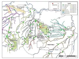
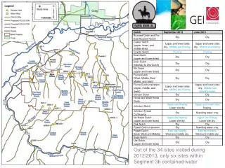
18kV cellule 18kV cellule A.Fabich, H.Kirk
PS beam • momentum p = 20 GeV/c • due to compatibility with nToF and kicker • 4 bunches within 8 PS buckets at our digression • tpulse= 0.5-2 microseconds • tbunch=50ns full length, peak-to-peak 250 ns • pulse length below 1 microsecond needs 2 man-months to develop • apart from this effort needed is in the order of days to week • money: 0 kChF Pump-Probe method for cavitation studies A.Fabich, H.Kirk
Cryogenics Solution towards TT2A and “permanent” LN2 supply (fixed dewar) • FH provided: • Schematic flow chart • List of recuperated material • 6000 l dewar • Cryogenic lines (bat 180: 4x25 m simple, 2x50 m shielded) • Heater • Vacuum pump ROOT • Manpower: 1.5 FTE*years • 50 kChF (for small parts) Responsibility in US: solenoid, controls, DVB FH is advising A.Fabich, H.Kirk
TT2A preliminary equipment proposal • Process control and instrumentation • 1) UNICOS (Schneider) ?, ABB ?, LabView ? • - control from distance • - proposed is ISR building 230 or 288 from which • 2) Instrumentation in conformity with CERN standards • Equipment to be cooled • 1) Pulsed magnet • Proximity equipment • 1) DVB valve box -feed valve with level control • -by-pass valve of TFL before recooling • -drain valve • -pumping line valve • -valve for nitrogen gas out • -temp sensors • -flow meter • 2) vacuum pump for insulation vacuum of magnet • 3) vacuum pump for reducing pressure in bath • 4) heat exchanger or el. heater • Intermediate Infra • 1) transfer line for cooling and filling • 2) exhaust for cold nitrogen gas during cooling and filling • 3) pump line (warm) • External Infra • 1) LN2 reservoir next to vertical shaft US CERN A.Fabich, H.Kirk
SHOW HARD-COPY of FLOW CHART A.Fabich, H.Kirk
18kV cellule Dewar 6000l Access route for LN2 delivery 18kV cellule A.Fabich, H.Kirk
Manpower • Not mentioned so far: • Physic studies • Project management A.Fabich, H.Kirk
Jet Chamber (top view) units: mm • Basic principle for all designs: • inner chamber for jet Connected by Straight nozzle Tilted nozzle Return pipe • outer inox tube • Optical ligth path + mirror(s) A.Fabich, H.Kirk
Optical System (2) Transverse cut Mirror support • Bore of magnet 13 cm contains: • jet chamber • steel frame • Makrolon plates • mirror system • support (adjustable in height) • around jet chamber • 2 mirrors • mercury recuperation system • The maximum observation along jet is defined by magnet bore minus the width of the jet chamber (minus some safety margins) • - Total area given by h and z • SAFETY MARGINS ~ 1mm • flexibility! air to reservoir 2cm h z Mirror 1 Maximum viewing area Jet chamber Mirror 2 Mirror pole bore / outer confinement Hg return A.Fabich, H.Kirk
Pulse list • Which parameters to vary and how? • Magnetic field (0-15, 3 T) • Pulse intensity (1-20, 4 TP) • Pulse length (0.5-20, 0.5 s) • Spot size • Beam position (5, 1 mm) • Get a realistic number of pulses needed!? A.Fabich, H.Kirk