Download
1 / 33
450 likes | 1.08k Vues
The soil strength depends upon many factors as particle texture , soil gradation, moisture content , bulk density and rate of loading. Measurement of Subgrade Soil Strength. Tests for measuring soil strength can be divided into three principal groups as follows: 1.Shear test;

E N D
The soil strength depends upon many factors as particle texture, soil gradation, moisture content, bulk density and rate of loading. Measurement of Subgrade Soil Strength
Tests for measuring soil strength can be divided into three principal groups as follows: 1.Shear test; 2.Plate loading test; 3.California bearing ratio (C.B.R.).
The main factors that affect the test results divided into two groups: • a-Factors hang up methods of testing as • -size and shape of specimen; • -method of loading; • -rate of loading; • -drainage conditions. • b-Factors hang up soil in place as • -soil type; • -dry density; • -moisture content; • -soil permeability; • -structure formed by soil particles.
The basic component of the system is a camber wherein a saturated sample, encapsulated in a rubber membrane and capped top and bottom with a porous stone, is seated on a pedestal and submerged in a fluid. Load is applied tri-axially by pressurizing the chamber fluid and un-axially through a load head whose shaft extends through the chamber via a permeation tight coupling. Vertical deformation and also lateral deformation can be determined 1.Triaxial Compression Test
The following types of tri-axial tests are performed: 1.Quick - test 2.Quick-drained test 3.Slow test. The quick -undrained test (quick test) given the design of pavements.
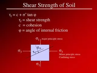
-Shear strength of the soil The coulomb equation determine the relation between shear strength at failure S and compression stress n at shear failure surface as following : S = C + n tan where C= cohesion of soil = angle of internal friction For clay soils saturated with water, not allow for drainage ( =0.0) S = C For granular soils without fines C=0 S = n tan
This test is made to evaluate the supporting power of subgrades and bases in the field and also to determine the modulus of subgrade reaction K. Circular plates with different diameters are used, usually, 30, 24, 18, and 12 inch, the load is applied to the 12 in. plate by means of hydraulic jacks. Deflection of the plate is measured by means of deflection dials placed usually at the one-third points of the plate near its outer edge (Figure 24).. 2-Plate Loading Test
1- Effect of plate size The unit load which a plate will sustain depends on the perimeter over area ratio as well as the strength of the soil. The unit load at a given deflection is calculated from the following equation: P = n + m * (p/a) where P = unit load n,m = empirical values obtained by test p/a = perimeter over area Factors affecting the test results of plate bearing test
2-Modulus of Subgrade Reaction (K) A plate 30 inches in diameter is generally employed in the test. By means of a loading system and a calibrated jack, the subgrade is subjected to a known pressures at a predetermined rate of speed. The modulus K is calculated as follows: K = P/ where P = unit load on the plate (psi) = deflection of the plate (in.)
There are two methods to determine the modulus K. a- Determination the unit load P at a deflection = 0.05 in. K = P0.05/0.05 b-Determination the deflection at unit load = 10 psi K = 10/ 10 The second method is more common. A unit load = 10 psi or total load = 7070 Ib is applied on the 30 in. diameter bearing plate during 10 sec. This constant load continue until the excess in rate of deflection is less than 0.002 in./min. in case of clay soils.
1. Effect of saturation The deformation of a soil sample in the laboratory is determined by 10 psi unit load. A second sample similarly compacted is then saturated and loaded under 10 psi. The modulus Ks in this case may be determined by the equation (figure 26): Ks = K * / s where , s = deflection in soil samples at normal state and saturated state under unit load = 10 psi. Correction the Modulus of Subgrade Reaction K
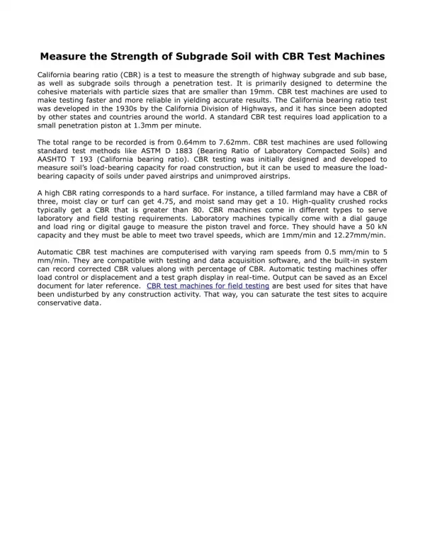
The test is designed to indicate the relative stability of soil that has been constructed with a particular density and water content and that has adjusted to its environment beneath the pavement. 3- California Bearing Ratio Test ( C.B.R.)
Test Procedure: The proper amount of water is mixed into the soil. The soil is then compacted in a cylindrical mold and soaked for 4 days with an imposed load roughly equivalent to that will be given by a prototype pavement. The amount of volume change is recorded during the soaking period.
The strength test (CBR) is a penetration test, whereby a circular piston with cross section area of 3 in2 is forced into the soaked soil at a constant rate of 0.05 inch/min. .The unit load at each 0.1 in. penetration up to 0.5 in. is recorded and the CBR computed at the ratio of an arbitrarily selected unit load to that of the standard. Table 6 shows the standard values of unit loads.
1-Surface drainage 2-subsurface or underground drainage HIGHWAY DRAINAGE
1.Surface drainage The portions of the highway structure that provide for surface drainage in rural locations include the roadway crown, shoulder and side slopes, longitudinal ditches ( channels), culverts and bridges. -Pavement and shoulder cross slopes Roadway surfaces are normally crowned to facilitate the removal of surface water from the wearing surface. Pavement cross slope should be steep enough to ensure expeditions drainage, but not so steep as to course driver annoyance, discomfort, or hazard. Shoulders are normally sloped to drain away from the pavement surface, precipitation that occupy on the shoulder area largely flows to the side ditches or the median.
-Side slopes and side ditches In rural areas, open side ditches may be constructed along embankment sections when needed to supplement natural drainage channels. Both flat -bottomed and V-section ditches are used (see Figure 31). In both cases, side slopes are made as flat as possible consistent with drainage requirements and limiting widths of right-of-ways. In very flat locations, ditch grades as low as 0.1 or 0.2% may be used, while in rolling or mountainous terrain the maximum grade may be dicthated only by the necessity for preventing erosion.
In urban areas and city streets, surface water may be collected in two ditches beside the shoulders in gutter. This gutter is made from concrete or natural stone. The water flow longitudinal in this gutter until reach to a hole named GULLIES. The longitudinal slopes of GUTTER is 1/100 to 1/120 URBAN AND CITY STREETS
There are three types of subsurface drainage : 1.intercepting drainage for the collection and removal of ground seepage from the side slopes of cuts (Fig.33). 2.subgrade drainage for holding the water table low in a subgrade both during and after construction (Fig.34 ). 3.base drainage to prevent flooding of pavement base by infiltration from above and seepage from blow ( Fig.35 ). Intercepting drainage often uses longitudinal trench drains parallel to the roadway as in Figure 36. -Sub-drainage or underground drainage
A trench drain consists of a perforated, slotted, porous pipe, usually 6 to 8 in. diameter, surrounded by pervious aggregate. Of critical importance is the design of the filter aggregate. The filter material must be properly graded and well compacted. Also, if compaction is not enough, the ground or pavement over the drain may subside. Finally, the drain should be sealed over the top if the trench with relatively impervious material to prevent the washing of fine material such as silt. -Trench drains and filters
1.It serves to increase the peripheral area which the drain may collect water from the surrounding soil. 2.A filter conducts converging water to the drainpipe without allowing excessive seepage force and piping. 3.The filter is designed to hold the foundation soil in place. -Functions of the Drainage Filter
On the basis of considerable experimentation, it has been found that an ample increase in permeability between foundation soil and filter is usually provided when the filter does not contain more than 5% fines and when (D15 of the filter / D15 of the foundation soil = 5 -40 where: D15= grain size at which 15% of the soil particles are as shown by mechanical analysis.
To prevent clogging of the filter with foundation soil, the pores of the filter should not be excessively larger than the coarse particles in the soil, (D15 of the filter / D85 of the foundation soil 5
For the case of slotted or perforated pipes, pipe clogging is prevented when, ( D85 of the filter / Max. opening of pipe drain 2