Computer Hardware Generations
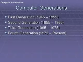
Computer Hardware Generations. The First Generation, 1946-59: Vacuum Tubes, Relays, Mercury Delay Lines: ENIAC (Electronic Numerical Integrator and Computer): First electronic computer, 18000 vacuum tubes, 1500 relays, 5000 additions/sec.

Computer Hardware Generations
E N D
Presentation Transcript
Computer Hardware Generations • The First Generation, 1946-59: Vacuum Tubes, Relays, Mercury Delay Lines: • ENIAC (Electronic Numerical Integrator and Computer): First electronic computer, 18000 vacuum tubes, 1500 relays, 5000 additions/sec. • First stored program computer: EDSAC (Electronic Delay Storage Automatic Calculator). • The Second Generation, 1959-64: Discrete Transistors. • The Third Generation, 1964-75: Small and Medium-Scale Integrated (MSI) Circuits. • The Fourth Generation, 1975-Present: The Microcomputer. VLSI-based Microprocessors.
- Control Input Memory (instructions, data) Datapath registers ALU, buses Output CPU Computer System I/O Devices The Von-Neumann Computer Model • Partitioning of the computing engine into components: • Central Processing Unit (CPU): Control Unit (instruction decode, sequencing of operations), Datapath (registers, arithmetic and logic unit, buses). • Memory: Instruction and operand storage. • Input/Output (I/O). • The stored program concept: Instructions from an instruction set are fetched from a common memory and executed one at a time.
Instruction Fetch Instruction Decode Operand Fetch Execute Result Store Next Instruction CPU Machine Instruction Execution Steps Obtain instruction from program storage Determine required actions and instruction size Locate and obtain operand data Compute result value or status Deposit results in storage for later use Determine successor or next instruction
Five classic components of all computers: 1. Control Unit; 2. Datapath; 3. Memory; 4. Input; 5. Output } Processor Hardware Components of Any Computer Keyboard, Mouse, etc. Computer Processor (active) Memory (passive) (where programs, data live when running) Devices Input Control Unit Disk Datapath Output Display, Printer, etc.
CPU Organization • Datapath Design: • Capabilities & performance characteristics of principal Functional Units (FUs): • (e.g., Registers, ALU, Shifters, Logic Units, ...) • Ways in which these components are interconnected (buses connections, multiplexors, etc.). • How information flows between components. • Control Unit Design: • Logic and means by which such information flow is controlled. • Control and coordination of FUs operation to realize the targeted Instruction Set Architecture to be implemented (can either be implemented using a finite state machine or a microprogram). • Hardware description with a suitable language, possibly using Register Transfer Notation (RTN).
I/O A Typical Personal Computer (PC) System Board Layout (90% of all computing systems worldwide). I/O: Misc Memory CPU I/O: Mass Storage
Computer System Components Proc Caches System Bus adapters I/O Buses Memory Controllers NICs Disks Displays Keyboards I/O Devices: Networks
Performance Increase of Workstation-Class Microprocessors 1987-1997 Integer SPEC92 Performance
Microprocessor Logic Density Alpha 21264: 15 million Pentium Pro: 5.5 million PowerPC 620: 6.9 million Alpha 21164: 9.3 million Sparc Ultra: 5.2 million Moore’s Law Moore’s Law: 2X transistors/Chip Every 1.5 years
Increase of Capacity of VLSI Dynamic RAM Chips year size(Megabit) 1980 0.0625 1983 0.25 1986 1 1989 4 1992 16 1996 64 1999 256 2000 1024 1.55X/yr, or doubling every 1.6 years
Computer Technology Trends: Rapid Change • Processor: • 2X in speed every 1.5 years; 1000X performance in last decade. • Memory: • DRAM capacity: > 2x every 1.5 years; 1000Xsize in last decade. • Cost per bit: Improves about 25% per year. • Disk: • Capacity: > 2X in size every 1.5 years. • Cost per bit: Improves about 60% per year. • 200Xsize in last decade. • Expected State-of-the-art PC by end of year 2002 : • Processor clock speed: > 3000 MegaHertz (3 GigaHertz) • Memory capacity: > 1000 MegaByte (1 GigaBytes) • Disk capacity: > 100 GigaBytes (0.1 TeraBytes)
A Simplified View of The Software/Hardware Hierarchical Layers
Application Operating System Compiler Firmware Instruction Set Architecture Instr. Set Proc. I/O system Datapath & Control Digital Design Circuit Design Layout Hierarchy of Computer Architecture High-Level Language Programs Assembly Language Programs Software Machine Language Program Software/Hardware Boundary Hardware Microprogram Register Transfer Notation (RTN) Logic Diagrams Circuit Diagrams
Levels of Program Representation temp = v[k]; v[k] = v[k+1]; v[k+1] = temp; High Level Language Program lw $15, 0($2) lw $16, 4($2) sw $16, 0($2) sw $15, 4($2) Compiler Assembly Language Program Assembler 0000 1001 1100 0110 1010 1111 0101 1000 1010 1111 0101 1000 0000 1001 1100 0110 1100 0110 1010 1111 0101 1000 0000 1001 0101 1000 0000 1001 1100 0110 1010 1111 Machine Language Program Machine Interpretation Control Signal Specification ALUOP[0:3] <= InstReg[9:11] & MASK Register Transfer Notation (RTN) ° °
Low Level - Hardware High Level - Software A Hierarchy of Computer Design Level Name Modules Primitives Descriptive Media 1 Electronics Gates, FF’s Transistors, Resistors, etc. Circuit Diagrams 2 Logic Registers, ALU’s ... Gates, FF’s …. Logic Diagrams 3 Organization Processors, Memories Registers, ALU’s … Register Transfer Notation (RTN) 4 Microprogramming Assembly Language Microinstructions Microprogram 5 Assembly language OS Routines Assembly language Assembly Language programming Instructions Programs 6 Procedural Applications OS Routines High-level Language Programming Drivers .. High-level Languages Programs 7 Application Systems Procedural Constructs Problem-Oriented Programs Firmware
Hardware Description • Hardware visualization: • Block diagrams (spatial visualization): Two-dimensional representations of functional units and their interconnections. • Timing charts (temporal visualization): Waveforms where events are displayed vs. time. • Register Transfer Notation (RTN): • A way to describe microoperations capable of being performed by the data flow (data registers, data buses, functional units) at the register transfer level of design (RT). • Also describes conditional information in the system which cause operations to come about. • A “shorthand” notation for microoperations. • Hardware Description Languages: • Examples: VHDL: VHSIC (Very High Speed Integrated Circuits) Hardware Description Language, Verilog.
Register Transfer Notation (RTN) • Dependent RTN: When RTN is used after the data flow is assumed to be frozen. No data transfer can take place over a path that does not exist. No statement implies a function the data flow hardware is incapable of performing. • Independent RTN: Describe actions on registers without regard to nonexistence of direct paths or intermediate registers. No predefined data flow. • The general format of an RTN statement: Conditional information: Action1; Action2 • The conditional statement is often an AND of literals (status and control signals) in the system (a p-term). The p-term is said to imply the action. • Possible actions include transfer of data to/from registers/memory data shifting, functional unit operations etc.
RTN Statement Examples A ¬B • A copy of the data in entity B (typically a register) is placed in Register A • If the destination register has fewer bits than the source, the destination accepts only the lowest-order bits. • If the destination has more bits than the source, the value of the source is sign extended to the left. CTL · T0: A = B • The contents of B are presented to the input of combinational circuit A • This action to the right of “:” takes place when control signal CTL is active and signal T0 is active.
RTN Statement Examples MD ¬ M[MA] • Memory locations are indicated by square brackets. • Means the memory data register receives the contents of the main memory (M) as addressed from the Memory Address (MA) register. AC(0), AC(1), AC(2),AC(3) • Register fields are indicated by parenthesis. • The concatenation operation is indicated by a comma. • Bit AC(0) is bit 0 of the accumulator AC • The above expression means AC bits 0, 1, 2, 3 • More commonly represented by AC(0-3) E · T3: CLRWRITE • The control signal CLRWRITE is activated when the condition E · T3 is active.
Computer Architecture Vs. Computer Organization • The term Computer architecture is sometimes erroneously restricted to computer instruction set design, with other aspects of computer design called implementation. • More accurate definitions: • Instruction set architecture: The actual programmer-visible instruction set and serves as the boundary between the software and hardware. • Implementation of a machine has two components: • Organization: includes the high-level aspects of a computer’s design such as: The memory system, the bus structure, the internal CPU unit which includes implementations of arithmetic, logic, branching, and data transfer operations. • Hardware: Refers to the specifics of the machine such as detailed logic design and packaging technology. • In general, Computer Architecture refers to the above three aspects: 1- Instruction set architecture 2- Organization. 3- Hardware.
Instruction Set Architecture (ISA) “... the attributes of a [computing] system as seen by the programmer, i.e. the conceptual structure and functional behavior, as distinct from the organization of the data flows and controls the logic design, and the physical implementation.” – Amdahl, Blaaw, and Brooks, 1964. • The instruction set architecture is concerned with: • Organization of programmable storage (memory & registers): • Includes the amount of addressable memory and number of • available registers. • Data Types & Data Structures: Encodings & representations. • Instruction Set: What operations are specified. • Instruction formats and encoding. • Modes of addressing and accessing data items and instructions • Exceptional conditions.
Computer Instruction Sets • Regardless of computer type, CPU structure, or hardware organization, every machine instruction must specify the following: • Opcode: Which operation to perform. Example: add, load, and branch. • Where to find the operand or operands, if any: Operands may be contained in CPU registers, main memory, or I/O ports. • Where to put the result, if there is a result: May be explicitly mentioned or implicit in the opcode. • Where to find the next instruction: Without any explicit branches, the instruction to execute is the next instruction in the sequence or a specified address in case of jump or branch instructions.
Instruction Fetch Instruction Decode Operand Fetch Execute Result Store Next Instruction Instruction Set Architecture (ISA) Specification Requirements • Instruction Format or Encoding: – How is it decoded? • Location of operands and result (addressing modes): – Where other than memory? – How many explicit operands? – How are memory operands located? – Which can or cannot be in memory? • Data type and Size. • Operations – What are supported • Successor instruction: – Jumps, conditions, branches. • Fetch-decode-execute is implicit.
General Types of Instructions • Data Movement Instructions, possible variations: • Memory-to-memory. • Memory-to-CPU register. • CPU-to-memory. • Constant-to-CPU register. • CPU-to-output. • etc. • Arithmetic Logic Unit (ALU) Instructions. • Branch Instructions: • Unconditional. • Conditional.
Instruction Meaning Machine MOV A,B Move 16-bit data from memory loc. A to loc. B VAX11 lwz R3,A Move 32-bit data from memory loc. A to register R3 PPC601 li $3,455 Load the 32-bit integer 455 into register $3 MIPS R3000 MOV AX,BX Move 16-bit data from register BX into register AX Intel X86 LEA.L (A0),A2 Load the address pointed to by A0 into A2 MC68000 Examples of Data Movement Instructions
Instruction Meaning Machine MULF A,B,C Multiply the 32-bit floating point values at mem. VAX11 locations A and B, and store result in loc. C nabs r3,r1 Store the negative absolute value of register r1 in r2 PPC601 ori $2,$1,255 Store the logical OR of register $1 with 255 into $2 MIPS R3000 SHL AX,4 Shift the 16-bit value in register AX left by 4 bits Intel X86 ADD.L D0,D1 Add the 32-bit values in registers D0, D1 and store MC68000 the result in register D0 Examples of ALU Instructions
Instruction Meaning Machine BLBS A, Tgt Branch to address Tgt if the least significant bit VAX11 at location A is set. bun r2 Branch to location in r2 if the previous comparison PPC601 signaled that one or more values was not a number. Beq $2,$1,32 Branch to location PC+4+32 if contents of $1 and $2 MIPS R3000 are equal. JCXZ Addr Jump to Addr if contents of register CX = 0. Intel X86 BVS next Branch to next if overflow flag in CC is set. MC68000 Examples of Branch Instructions
Operation Types in The Instruction Set Operator TypeExamples Arithmetic and logical Integer arithmetic and logical operations: add, or Data transfer Loads-stores (move on machines with memory addressing) Control Branch, jump, procedure call, and return, traps. System Operating system call, virtual memory management instructions Floating point Floating point operations: add, multiply. Decimal Decimal add, decimal multiply, decimal to character conversion String String move, string compare, string search Graphics Pixel operations, compression/ decompression operations
instruction load 22% conditional branch 20% compare 16% store 12% add 8% and 6% sub 5% move register-register 4% call 1% return 1% Total 96% Instruction Usage Example: Top 10 Intel X86 Instructions Rank Integer Average Percent total executed 1 2 3 4 5 6 7 8 9 10 Observation: Simple instructions dominate instruction usage frequency.
Types of Instruction Set ArchitecturesAccording To Operand Addressing Fields Memory-To-Memory Machines: • Operands obtained from memory and results stored back in memory by any instruction that requires operands. • No local CPU registers are used in the CPU datapath. • Include: • The 4 Address Machine. • The 3-address Machine. • The 2-address Machine. The 1-address (Accumulator) Machine: • A single local CPU special-purpose register (accumulator) is used as the source of one operand and as the result destination. The 0-address or Stack Machine: • A push-down stack is used in the CPU. General Purpose Register (GPR) Machines: • The CPU datapath contains several local general-purpose registers which can be used as operand sources and as result destinations. • A large number of possible addressing modes. • Load-Store or Register-To-Register Machines: GPR machines where only data movement instructions (loads, stores) can obtain operands from memory and store results to memory.
Memory CPU Op1Addr: Op1 + Op2 Op2Addr: ResAddr: Res : : Instruction Format Bits: 8 24 24 24 24 add ResAddr Op1Addr Op2Addr NextiAddr NextiAddr: Nexti Opcode Which operation Where to find next instruction Where to put result Where to find operands Types of Instruction Set ArchitecturesMemory-To-Memory Machines: The 4-Address Machine • No program counter (PC) or other CPU registers are used. • Instructions specify: • Location of first operand. - Location of second operand. • Place to store the result. - Location of next instruction. Instruction: add Res, Op1, Op2, Nexti Meaning: (Res ¬ Op1 + Op2)
CPU Memory Op1Addr: Op1 + Op2 Op2Addr: ResAddr: Res Where to find next instruction Instruction Format : : Bits: 8 24 24 24 Program Counter (PC) 24 add ResAddr Op1Addr Op2Addr Opcode Which operation NextiAddr: Nexti Where to put result Where to find operands Types of Instruction Set ArchitecturesMemory-To-Memory Machines: The 3-Address Machine • A program counter is included within the CPU which points to the next instruction. • No CPU storage (general-purpose registers). Instruction: add Res, Op1, Op2 Meaning: (Res ¬ Op1 + Op2)
Memory CPU Op1Addr: Op1 Op2Addr: + Op2,Res : : Where to find next instruction Instruction Format Bits: 8 24 24 NextiAddr: Nexti Program Counter (PC) 24 add Op2Addr Op1Addr Opcode Which operation Where to find operands Where to put result Types of Instruction Set ArchitecturesMemory-To-Memory Machines: The 2-Address Machine • The 2-address Machine: Result is stored in the memory address of one of the operands. Instruction: add Op2, Op1 Meaning: (Op2 ¬ Op1 + Op2)
Memory CPU Op1Addr: Op1 Where to find operand2, and where to put result + Accumulator Instruction Format : : Bits: 8 24 Where to find next instruction add Op1Addr Opcode Which operation NextiAddr: Nexti Program Counter (PC) 24 Where to find operand1 Types of Instruction Set ArchitecturesThe 1-address (Accumulator) Machine • A single accumulator in the CPU is used as the source of one operand and result destination. Instruction: add Op1 Meaning: (Acc ¬ Acc + Op1)
CPU Instruction Format Instruction Format Instruction: push Op1 Meaning: (TOS ¬ Op1) Memory Bits: Bits: 8 24 8 24 Stack push pop push ResAddr Op1Addr Op1Addr: Op1 pop Opcode Opcode Where to find operand Memory Destination add Op2, Res TOS SOS etc. Op2 Op2Addr: Instruction: add Meaning: (TOS ¬ TOS + SOS) Op1 Instruction Format ResAddr: Res + Bits: 8 add : : Opcode 8 Instruction: pop Res Meaning: (Res ¬ TOS) NextiAddr: Nexti Program Counter (PC) 24 Types of Instruction Set ArchitecturesThe 0-address (Stack) Machine • A push-down stack is used in the CPU.
CPU Instruction Format Instruction Format Instruction: load R8, Op1 Meaning: (R8 ¬ Op1) Memory Bits: Bits: 8 3 24 8 3 24 Registers load store ResAddr Op1Addr R8 R2 load Op1Addr: Op1 R8 R7 R6 R5 R4 R3 R2 R1 Opcode Opcode Where to find operand1 Destination add Instruction: add R2, R4, R6 Meaning: (R2 ¬ R4 + R6) Instruction Format + Bits: 8 3 3 3 add R2 R4 R6 : : store Opcode Des Operands Instruction: store R2, Op2 Meaning: (Op2 ¬ R2) NextiAddr: Nexti Program Counter (PC) 24 Types of Instruction Set ArchitecturesGeneral Purpose Register (GPR) Machines • CPU contains several general-purpose registers which can be used as operand sources and result destination.
Expression Evaluation Example with 3-, 2-, 1-, 0-Address, And GPR Machines For the expression A = (B + C) * D - E where A-E are in memory GPR 0-Address Stack push B push C add push D mul push E sub pop A 8 instructions Code size: 23 bytes 5 memory accesses 1-Address Accumulator load B add C mul D sub E store A 5 instructions Code size: 20 bytes 5 memory accesses Load-Store load R1, B load R2, C add R3, R1, R2 load R1, D mul R3, R3, R1 load R1, E sub R3, R3, R1 store A, R3 8 instructions Code size: about 29 bytes 5 memory accesses 3-Address add A, B, C mul A, A, D sub A, A, E 3 instructions Code size: 30 bytes 9 memory accesses 2-Address load A, B add A, C mul A, D sub A, E 4 instructions Code size: 28 bytes 12 memory accesses Register-Memory load R1, B add R1, C mul R1, D sub R1, E store A, R1 5 instructions Code size: about 22 bytes 5 memory accesses
Typical ISA Addressing Modes Addressing Sample Mode Instruction Meaning Register Immediate Displacement Indirect Indexed Absolute Memory indirect Autoincrement Autodecrement Scaled Add R4, R3 Add R4, #3 Add R4, 10 (R1) Add R4, (R1) Add R3, (R1 + R2) Add R1, (1001) Add R1, @ (R3) Add R1, (R2) + Add R1, - (R2) Add R1, 100 (R2) [R3] R4 ¬ R4 + R3 R4 ¬ R4 + 3 R4 ¬ R4 + Mem[10+ R1] R4 ¬ R4 + Mem[R1] R3 ¬ R3 +Mem[R1 + R2] R1 ¬ R1 + Mem[1001] R1 ¬ R1 + Mem[Mem[R3]] R1 ¬ R1 + Mem[R2] R2 ¬ R2 + d R2 ¬ R2 - d R1 ¬ R1 + Mem[R2] R1 ¬ R1+ Mem[100+ R2 + R3*d]
Addressing Modes Usage Example For 3 programs running on VAX ignoring direct register mode: Displacement 42% avg, 32% to 55% Immediate: 33% avg, 17% to 43% Register deferred (indirect): 13% avg, 3% to 24% Scaled: 7% avg, 0% to 16% Memory indirect: 3% avg, 1% to 6% Misc: 2% avg, 0% to 3% 75% displacement & immediate 88% displacement, immediate & register indirect. Observation: In addition Register direct, Displacement, Immediate, Register Indirect addressing modes are important. 75% 88%
Displacement Address Bits Needed Displacement Address Size Example Avg. of 5 SPECint92 programs v. avg. 5 SPECfp92 programs 1% of addresses > 16-bits 12 - 16 bits of displacement needed
Instruction Set Encoding Considerations affecting instruction set encoding: • To have as many registers and addressing modes as possible. • The Impact of of the size of the register and addressing mode fields on the average instruction size and on the average program. • To encode instructions into lengths that will be easy to handle in the implementation. On a minimum to be a multiple of bytes. • Fixed length encoding: Faster and easiest to implement in hardware. • Variable length encoding: Produces smaller instructions. • Hybrid encoding.
Three Examples of Instruction Set Encoding Operations & no of operands Address specifier 1 Address field 1 Address specifier n Address field n • Variable Length Encoding: VAX (1-53 bytes) Operation Address field 1 Address field 2 Address field3 Fixed Length Encoding: DLX, MIPS, PowerPC, SPARC Operation Address field Address Specifier Address Specifier 1 Address Specifier 2 Operation Address field Address Specifier Address field 2 Operation Address field 1 • Hybrid Encoding: IBM 360/370, Intel 80x86
Instruction Set Architecture Trade-offs • 3-address machine: shortest code sequence; a large number of bits per instruction; large number of memory accesses. • 0-address (stack) machine: Longest code sequence; shortest individual instructions; more complex to program. • General purpose register machine (GPR): • Addressing modified by specifying among a small set of registers with using a short register address (all machines since 1975). • Advantages of GPR: • Low number of memory accesses. Faster, since register access is currently still much faster than memory access. • Registers are easier for compilers to use. • Shorter, simpler instructions. • Load-Store Machines: GPR machines where memory addresses are only included in data movement instructions between memory and registers (all machines after 1980).
ISA Examples Machine Number of General Architecture year Purpose Registers EDSAC IBM 701 CDC 6600 IBM 360 DEC PDP-11 DEC VAX Motorola 68000 MIPS SPARC 1 1 8 16 8 16 16 32 32 accumulator accumulator load-store register-memory register-memory register-memory memory-memory register-memory load-store load-store 1949 1953 1963 1964 1970 1977 1980 1985 1987
Examples of GPR Machines Number ofMaximum number memory addresses of operands allowed SPARK, MIPS PowerPC, ALPHA Intel 80x86, Motorola 68000 2 or 3 2 or 3 VAX 0 3 1 2
Complex Instruction Set Computer (CISC) • Emphasizes doing more with each instruction. • Motivated by the high cost of memory and hard disk capacity when original CISC architectures were proposed: • When M6800 was introduced: 16K RAM = $500, 40M hard disk = $ 55, 000 • When MC68000 was introduced: 64K RAM = $200, 10M HD = $5,000 • Original CISC architectures evolved with faster, more complex CPU designs, but backward instruction set compatibility had to be maintained. • Wide variety of addressing modes: • 14 in MC68000, 25 in MC68020 • A number instruction modes for the location and number of operands: • The VAX has 0- through 3-address instructions. • Variable-length or hybrid instruction encoding is used.
Example CISC ISAs Motorola 680X0 18 addressing modes: • Data register direct. • Address register direct. • Immediate. • Absolute short. • Absolute long. • Address register indirect. • Address register indirect with postincrement. • Address register indirect with predecrement. • Address register indirect with displacement. • Address register indirect with index (8-bit). • Address register indirect with index (base). • Memory inderect postindexed. • Memory indirect preindexed. • Program counter indirect with index (8-bit). • Program counter indirect with index (base). • Program counter indirect with displacement. • Program counter memory indirect postindexed. • Program counter memory indirect preindexed. Operand size: • Range from 1 to 32 bits, 1, 2, 4, 8, 10, or 16 bytes. Instruction Encoding: • Instructions are stored in 16-bit words. • the smallest instruction is 2- bytes (one word). • The longest instruction is 5 words (10 bytes) in length.
Example CISC ISA:Intel X86, 386/486/Pentium 12 addressing modes: • Register. • Immediate. • Direct. • Base. • Base + Displacement. • Index + Displacement. • Scaled Index + Displacement. • Based Index. • Based Scaled Index. • Based Index + Displacement. • Based Scaled Index + Displacement. • Relative. Operand sizes: • Can be 8, 16, 32, 48, 64, or 80 bits long. • Also supports string operations. Instruction Encoding: • The smallest instruction is one byte. • The longest instruction is 12 bytes long. • The first bytes generally contain the opcode, mode specifiers, and register fields. • The remainder bytes are for address displacement and immediate data.