
Weld Quality Weld Testing
E N D
Presentation Transcript
5. The quality of any weldment depends on a number of factors:
Was it designed adequately to meet its intended purpose?
Was it fabricated with care selecting appropriate materials and welding procedures to avoid defects?
Was it operated and maintained as originally intended?
Only when all of these conditions are met can one say that weldment was of sufficient quality.The quality of any weldment depends on a number of factors:
Was it designed adequately to meet its intended purpose?
Was it fabricated with care selecting appropriate materials and welding procedures to avoid defects?
Was it operated and maintained as originally intended?
Only when all of these conditions are met can one say that weldment was of sufficient quality.
6. To assure quality of weld workmanship the welds are examined with the factors listed above in mind.To assure quality of weld workmanship the welds are examined with the factors listed above in mind.
7. Effect of Discontinuities on Properties Discontinuities in a welded joint can influence mechanical properties
Codes establish size limits for acceptable discontinuities
Discontinuities unacceptable by a given code are called defects and are subject to repair Stress applied to a material is magnified by flaws in the material, e.g., cracks. A stress intensity factor quantifies this magnification of the applied stress. The fracture toughness of a material is the critical value of this stress intensity factor that causes fracture.
The term Engineering Critical Assessment is used for the analysis of a structure that has flaws (cracks) and will be subjected to stress. Several factors must be considered in order to make a realistic prediction of the likelihood of catastrophic (brittle) failure of such a structure: temperature, crack geometry, magnitude of the stress, strain rate, and yield strength of the material.Stress applied to a material is magnified by flaws in the material, e.g., cracks. A stress intensity factor quantifies this magnification of the applied stress. The fracture toughness of a material is the critical value of this stress intensity factor that causes fracture.
The term Engineering Critical Assessment is used for the analysis of a structure that has flaws (cracks) and will be subjected to stress. Several factors must be considered in order to make a realistic prediction of the likelihood of catastrophic (brittle) failure of such a structure: temperature, crack geometry, magnitude of the stress, strain rate, and yield strength of the material.
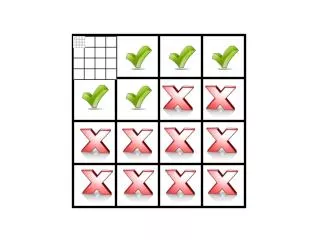
8. When discontinuities are discovered in a weldment, they can be generally sorted into one of the three classification listed above. Did they occur as a result of the selection of the wrong process or procedure, did they occur because of some metallurgical inconsistency, or did they occur because of a miscalculation in the design process? It should be noted that even though a discontinuity is detected, is is not classified as a defect unless it of sufficient size or severity to render the weldment unserviceable or suspect in service. Codes and standards are clear on the point where discontinuities become defects and they should be consulted for quality concerns.When discontinuities are discovered in a weldment, they can be generally sorted into one of the three classification listed above. Did they occur as a result of the selection of the wrong process or procedure, did they occur because of some metallurgical inconsistency, or did they occur because of a miscalculation in the design process? It should be noted that even though a discontinuity is detected, is is not classified as a defect unless it of sufficient size or severity to render the weldment unserviceable or suspect in service. Codes and standards are clear on the point where discontinuities become defects and they should be consulted for quality concerns.
9. The tables above list various discontinuities classified as welding process or procedure related discontinuities. Some examples of these are shown in the next slide.The tables above list various discontinuities classified as welding process or procedure related discontinuities. Some examples of these are shown in the next slide.
10. Examples of welding process or procedure related discontinuities. Examples of welding process or procedure related discontinuities.
11. The above table list various metallurgical related discontinuities.The above table list various metallurgical related discontinuities.
12. And finally, the above tale lists design related discontinuities.And finally, the above tale lists design related discontinuities.
16. Porosity Porosity is the entrapment of small volumes of gas in solidifying weld metal
Prevention
Drying consumables
Cleaning, degreasing material being welded
Electrode or filler metals with higher level of deoxidants
Sealing air leaks, reducing excess shielding gas flow Molten weld metal is able to hold more gas than solid weld metal. For this reason, gas bubbles tend to evolve as the liquid metal solidifies. These gas bubbles trapped within the solid weld metal are referred to as porosity. Although porosity is sometimes noted at the surface of a weld, visual inspection cannot detect internal porosity. Radiography and ultrasonic methods are required. Localized regions of porosity can be cut from a weld; a repair is then made. For general porosity throughout a weld, the entire weld must be gouged out and rewelded.Molten weld metal is able to hold more gas than solid weld metal. For this reason, gas bubbles tend to evolve as the liquid metal solidifies. These gas bubbles trapped within the solid weld metal are referred to as porosity. Although porosity is sometimes noted at the surface of a weld, visual inspection cannot detect internal porosity. Radiography and ultrasonic methods are required. Localized regions of porosity can be cut from a weld; a repair is then made. For general porosity throughout a weld, the entire weld must be gouged out and rewelded.
17. Slag inclusions Slag inclusions are irregularly shaped, not spherical like porosity
Prevention
Position work and/or change electrode/flux to increase slag control
Better slag removal between passes
Dress weld surface smooth if it is likely to cause slag traps
Remove heavy mill scale on plate Slag inclusions, as the name implies, are small pieces of welding slag which are trapped in the weld metal. Unlike porosity, which is usually spherical, slag inclusions are irregularly shaped. Since these are internal discontinuities, radiography or ultrasonic testing is required for detection. Weld regions containing slag inclusions must be cut out and rewelded.Slag inclusions, as the name implies, are small pieces of welding slag which are trapped in the weld metal. Unlike porosity, which is usually spherical, slag inclusions are irregularly shaped. Since these are internal discontinuities, radiography or ultrasonic testing is required for detection. Weld regions containing slag inclusions must be cut out and rewelded.
18. Lack of Fusion Lack of fusion is caused by incorrect welding conditions
Prevention
Procedure for complete fusion should be verified by testing
Increased energy input
Correct electrode angle and work position Lack of fusion can occur at the weld sidewall, root, or between individual passes. Magnetic particle and dye or fluorescent penetrant may be used to detect this discontinuity if it reaches the surface. Otherwise, radiography or ultrasonic methods must be used. Affected regions must be cut out and rewelded.Lack of fusion can occur at the weld sidewall, root, or between individual passes. Magnetic particle and dye or fluorescent penetrant may be used to detect this discontinuity if it reaches the surface. Otherwise, radiography or ultrasonic methods must be used. Affected regions must be cut out and rewelded.
19. Incomplete Root Penetration Incomplete root penetration can be caused by
Excessively thick root face, insufficient root gap
Incorrect welding conditions
Misalignment of second weld
Prevention
Improved joint preparation
Test weld verifications for correct parameters
Reassessment of back gouging Incomplete root penetration is the failure of a weld to extend into the root of a joint. For a double weld, it is an internal discontinuity and can be detected only by radiography or ultrasonic testing. It can be detected by magnetic particle, and dye or fluorescent penetrant methods if the root side is accessible. A long pipeline would be an example of when the weld root (inside the pipe) would not be accessible. This defect is repaired by cutting it out and rewelding.Incomplete root penetration is the failure of a weld to extend into the root of a joint. For a double weld, it is an internal discontinuity and can be detected only by radiography or ultrasonic testing. It can be detected by magnetic particle, and dye or fluorescent penetrant methods if the root side is accessible. A long pipeline would be an example of when the weld root (inside the pipe) would not be accessible. This defect is repaired by cutting it out and rewelding.
20. Overlap Overlap is an imperfection at the weld toe or root caused by metal flowing onto the surface of the base metal without fusing to it
Prevention
Adjust electrode manipulation to ensure fusion of base metal
Limit size of fillet to 9-mm leg length Overlap is often associated with horizontal welding; welding in the flat position can help to eliminate this problem. Overlap can be detected visually and can be supplemented with dye penetrant. It is corrected by cutting back to sound weld metal. Rewelding may be necessary.Overlap is often associated with horizontal welding; welding in the flat position can help to eliminate this problem. Overlap can be detected visually and can be supplemented with dye penetrant. It is corrected by cutting back to sound weld metal. Rewelding may be necessary.
21. Undercut Undercut is an irregular groove at the weld toe in the parent metal or previous pass caused by
excessive weaving
melting of top edge of fillet weld with high current
Prevention
Weld in flat position
Change shielding gas to one which produces better wetting
Terminate welds so they don�t finish at a free edge Undercut is another defect that can be associated with horizontal welding among other factors such as high current and excessive weaving. Flat position welding can aid in eliminating this discontinuity. It is detected visually and measured by a depth gauge. Deep undercut is ground out and weld repaired.Undercut is another defect that can be associated with horizontal welding among other factors such as high current and excessive weaving. Flat position welding can aid in eliminating this discontinuity. It is detected visually and measured by a depth gauge. Deep undercut is ground out and weld repaired.
22. Excessive Penetration Excessive penetration is caused by
Incorrect assembly or preparation
Edge preparation too thin to support weld underbead
Excessive root gap
Energy input too high
Lack of operator skill
Prevention
Control of preparation, backing bars Maintaining uniform root penetration requires great skill on the part of the welder, especially when welding butted pipe ends. Excessive root penetration is detected visually; however in the case of pipelines, radiography is used if the pipe bore cannot be examined. Excessive penetration is corrected by such dressing operations as grinding. In piping, it is corrected by broaching.Maintaining uniform root penetration requires great skill on the part of the welder, especially when welding butted pipe ends. Excessive root penetration is detected visually; however in the case of pipelines, radiography is used if the pipe bore cannot be examined. Excessive penetration is corrected by such dressing operations as grinding. In piping, it is corrected by broaching.
23. Root Concavity Root concavity is caused by
Excessively thick root face
Insufficient arc energy for penetration
Excessive backing gas pressure
Prevention
Reduce root face thickness, control backing gas pressure
Establish a procedure by test welding Root concavity involves the weld metal being forced out of the root by such mechanisms as excessive backing pressure or the wicking action of the joint preparation. It is detected visually if the root is accessible; otherwise, it is detected by radiography. It can be corrected by adding extra weld metal from the root side. If the root is inaccessible, the joint must be cut out and rewelded. Root concavity involves the weld metal being forced out of the root by such mechanisms as excessive backing pressure or the wicking action of the joint preparation. It is detected visually if the root is accessible; otherwise, it is detected by radiography. It can be corrected by adding extra weld metal from the root side. If the root is inaccessible, the joint must be cut out and rewelded.
24. Spatter Spatter consists of small droplets of electrode material that land beside the weld and may or may not fuse to the base material
Prevention
Reduce energy input
Shorter arc length
Reposition current return clamp to reduce magnetic arc blow or switch to AC current As metal drops transfer from the electrode to the weld pool, some are blown clear of the weld and form drops of spatter on the base plate. All open arc consumable electrode processes produce some spatter.
Spatter can occur when the energy input is too high or when the arc length is excessive. Arc blow can also cause spatter, as can insufficient inductance in GMAW or CO2 welding.
Spatter can be detected visually. It can be removed by scraping or by light grinding. Anti-spatter coatings are available on the market that prevent spatter from adhering to the base material.As metal drops transfer from the electrode to the weld pool, some are blown clear of the weld and form drops of spatter on the base plate. All open arc consumable electrode processes produce some spatter.
Spatter can occur when the energy input is too high or when the arc length is excessive. Arc blow can also cause spatter, as can insufficient inductance in GMAW or CO2 welding.
Spatter can be detected visually. It can be removed by scraping or by light grinding. Anti-spatter coatings are available on the market that prevent spatter from adhering to the base material.
26. In the process of determining if an acceptable weld can be made with new materials or by some new process or procedure, it is often helpful to make a test weld and then run some standard mechanical tests on the weld in order to reveal the presence of discontinuities or defects. Following are some of the most common test performed.In the process of determining if an acceptable weld can be made with new materials or by some new process or procedure, it is often helpful to make a test weld and then run some standard mechanical tests on the weld in order to reveal the presence of discontinuities or defects. Following are some of the most common test performed.
27. Tensile tests are perhaps the most often used mechanical test for determining weld quality. As seen from this figure, different size (shape) tensile samples are used depending on if all weld metal properties are required, or cross weld properties, or all base metal properties are required. In addition, often samples are taken in different directions in the plate or weldment as plate rolling often produced anisotropy in mechanical properties and the property in one direction may not be the same as in another.Tensile tests are perhaps the most often used mechanical test for determining weld quality. As seen from this figure, different size (shape) tensile samples are used depending on if all weld metal properties are required, or cross weld properties, or all base metal properties are required. In addition, often samples are taken in different directions in the plate or weldment as plate rolling often produced anisotropy in mechanical properties and the property in one direction may not be the same as in another.
28. When load carry capacity of weld, particularly fillet welds, are required, weld test coupons like the ones illustrated here are often used. These will give values for the fillet weld strength when loaded longitudinally and transverse.When load carry capacity of weld, particularly fillet welds, are required, weld test coupons like the ones illustrated here are often used. These will give values for the fillet weld strength when loaded longitudinally and transverse.
29. Another test which is often used to determine the quality of test welds is the bend test. In this test, slices are cut across the weld and the slice is then bent in a three point bending unit. The orientation of the slice can be changed from root bend, where the root of the weld is bent so that it is in tension; a face bend, where the face of the weld is in tension; and a side bend where the weld cross section is placed in tension. A root bend will reveal discontinuities in the root such as incomplete penetration. The face bend will reveal discontinuities in the face such as undercut and microcracks. The side bend will reveal lack of fusion and other internal discontinuities.Another test which is often used to determine the quality of test welds is the bend test. In this test, slices are cut across the weld and the slice is then bent in a three point bending unit. The orientation of the slice can be changed from root bend, where the root of the weld is bent so that it is in tension; a face bend, where the face of the weld is in tension; and a side bend where the weld cross section is placed in tension. A root bend will reveal discontinuities in the root such as incomplete penetration. The face bend will reveal discontinuities in the face such as undercut and microcracks. The side bend will reveal lack of fusion and other internal discontinuities.
30. For welds which might find applications in fatigue conditions, a series of fatigue tests might be run. Note that there is a clear distinction between samples welded with different procedures.For welds which might find applications in fatigue conditions, a series of fatigue tests might be run. Note that there is a clear distinction between samples welded with different procedures.
31. Fatigue Appearance Distinct fracture surface has a characteristic texture
Concentric line pattern
Smooth portion referred to as clamshell texture The surface of a fatigue fracture has a characteristic appearance. A concentric line pattern is noted to grow outward from an initiation point. In welding, this initiation point could be associated with a slag intrusion, undercut, or other discontinuity associated with the welding process.
The concentric line pattern provides a visual record of the accumulated crack growth from the initiation site with continued cyclic loading. The fracture surface near the initiation site is generally smooth and is noted to have a clamshell-like texture. If more than one initiation site is present, the fatigue cracks, often growing on different planes, will link up to form a unified crack front.
When the cross section of the material is no longer able to support the load, failure (sometimes sudden, catastrophic) occurs. In these instances, the ends of the fatigue crack can spontaneously start to run at high speeds due to the stress concentration. In cases of brittle fracture in pipelines, longitudinal cracks have been know to run several hundreds of yards before stopping.The surface of a fatigue fracture has a characteristic appearance. A concentric line pattern is noted to grow outward from an initiation point. In welding, this initiation point could be associated with a slag intrusion, undercut, or other discontinuity associated with the welding process.
The concentric line pattern provides a visual record of the accumulated crack growth from the initiation site with continued cyclic loading. The fracture surface near the initiation site is generally smooth and is noted to have a clamshell-like texture. If more than one initiation site is present, the fatigue cracks, often growing on different planes, will link up to form a unified crack front.
When the cross section of the material is no longer able to support the load, failure (sometimes sudden, catastrophic) occurs. In these instances, the ends of the fatigue crack can spontaneously start to run at high speeds due to the stress concentration. In cases of brittle fracture in pipelines, longitudinal cracks have been know to run several hundreds of yards before stopping.
32. Welds which must find service in corrosive environments often are immersed in corrosive media and given a corrosion test. Depending upon the location of greatest corrosion, valuable information can be obtained about service life of the weldment.Welds which must find service in corrosive environments often are immersed in corrosive media and given a corrosion test. Depending upon the location of greatest corrosion, valuable information can be obtained about service life of the weldment.