Download
1 / 9
100 likes | 896 Vues
Weld Joint Geometry and Weld Symbols. Parts of a Weld Joint Welding Technology Lee Co. ATC Graphics compliments of AWS. Submitted by Craig Herald Welding Instructor Lee County Area Technology Center. To the AWS Welding Educator’s Electronic File Library www.aws.org/Educators.

E N D
Weld Joint Geometry and Weld Symbols Parts of a Weld Joint Welding Technology Lee Co. ATC Graphics compliments of AWS
Submitted by Craig Herald Welding Instructor Lee County Area Technology Center To the AWS Welding Educator’s Electronic File Library www.aws.org/Educators Graphics provided compliments of the American Welding Society Education Department
It may be necessary to describe the exact joint design • Once you can identify the types of joints, you must be able to identify individual features that make up the joint geometry for a particular joint • These features and elements are often essential variables in welding procedure, as well as production welding • Welding personal may required to apply this knowledge once in the industry
Parts of a weld • Joint root • Groove face • Root face • Root edge • Root opening • Bevel • Bevel angle • Groove angle • Groove radius
Joint root is “ that portion of a joint to be welded where the members are closest to each other • The joint root may be either a point, line, or an area • The joint roots are shown as shaded areas in (A)-(D) and lines in (E) (F)
Groove Face, Root Face, and Root Edge • Groove face is “ that surface of a member included in the groove” • Root face (land) is “that portion of the groove face within the joint root” • Root edge is a root face of zero width
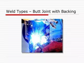
Root Opening and Bevel • Root opening is the separation between the work pieces at the joint root • Bevel (chamfer) is an angular edge preparation
Bevel Angle, Groove Angle, and Groove Radius • Bevel angle is the angle between the bevel of a joint member and a plane perpendicular to the surface of the member • Groove angle the total included angle of the groove between members • Groove radius applies only to J-&U- groove welds
Extra information is necessary to describe the exact joint design • For a single-bevel-groove-weld, the bevel angle and the groove angle are equal • Groove radius is “the radius used to form the shape of a J- or U- groove weld.” Normally the weld configuration is specified by both an angle and a radius