H-1 Heliac: Parameters
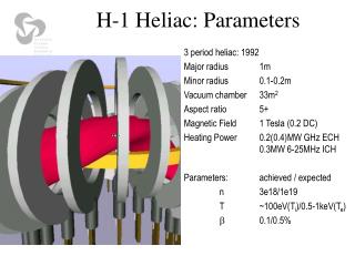
H-1 Heliac: Parameters. 3 period heliac: 1992 Major radius 1m Minor radius 0.1-0.2m Vacuum chamber 33m 2 Aspect ratio 5+ Magnetic Field 1 Tesla (0.2 DC) Heating Power 0.2(0.4)MW GHz ECH 0.3MW 6-25MHz ICH Parameters: achieved / expected n 3e18/1e19 T ~100eV(T i )/0.5-1keV(T e )

H-1 Heliac: Parameters
E N D
Presentation Transcript
H-1 Heliac: Parameters 3 period heliac: 1992 Major radius 1m Minor radius 0.1-0.2m Vacuum chamber 33m2 Aspect ratio 5+ Magnetic Field 1 Tesla (0.2 DC) Heating Power 0.2(0.4)MW GHz ECH 0.3MW 6-25MHz ICH Parameters: achieved / expected n3e18/1e19 T~100eV(Ti)/0.5-1keV(Te) 0.1/0.5%
Complex geometry requires minimum 2D diagnostic H-1 Heliac: Parameters 3 period heliac: 1992 Major radius 1m Minor radius 0.1-0.2m Vacuum chamber 33m2 Aspect ratio 5+ Magnetic Field 1 Tesla (0.2 DC) Heating Power 0.2(0.4)MW GHz ECH 0.3MW 6-25MHz ICH Parameters: achieved / expected n3e18/1e19 T~100eV(Ti)/0.5-1keV(Te) 0.1/0.5% Cross-section of the magnet structure showing a 3x11 channel tomographic diagnostic
Plasma production and heating:resonant and non-resonant RF • Non-resonant heating is flexible in B0, works better at low fields. • Resonant heating is much more successful at high fields. <ne> 1018m-3 helicon/frame antenna Update with helium, Tesla = Chon axis Magnetic Field (T)
2D electron density tomography Helical axis non-circular need true 2D coherent drift mode in argon, 0.08T H density profile evolution (0.5T rf) Raw chordal data Tomographically inverted data
Ion Temperature Camera Intensity temperature rotation Hollow Ti at low B0 radius 0 10 20 30 time (ms)
Confinement transitions in H-1 Parameter space map, ~ 1.4 “Pressure” (Is) profile evolution during transition PRF (kW) transition B0(T) • many features in common with large machines • associated with edge shear in Er • easily reproduced and investigated
Bulk Rotation Impeded 0 0 ExB and ion bulk rotation velocity in high confinement mode: magnetic structure causes viscous damping of rotation Radial force balance Vp, Vt << VExB ~ 1/(neB) dPi/dr Mass (ion) flow velocities much smaller than corresponding VExB