Download
1 / 48
480 likes | 674 Vues
Chapter 5 Radio Signals and Equipment. Signal Review Modulation is the process by which information (voice or data) is impressed into the transmitted radio signal. Demodulation is the process by which information is extracted from the received signal.

E N D
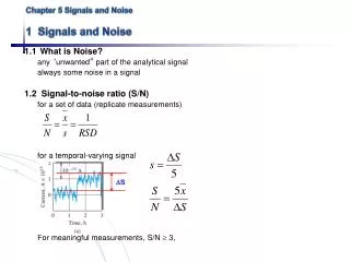
Chapter 5Radio Signals and Equipment Signal Review • Modulation is the process by which information (voice or data) is impressed into the transmitted radio signal. • Demodulation is the process by which information is extracted from the received signal. • The more information a signal carries, the wider is its bandwidth.
Bandwidth is the width of the frequency band outside of which the average transmitted power is attenuated at least 26 dB.
Amplitude Modulated Modes • Amplitude modulation (AM) contains a carrier with two identical sidebands above and below the carrier. • Single sideband (SSB) removes the carrier and one of the sidebands - upper sideband (USB) and lower sideband (LSB). More transmitter power is contained in a smaller bandwidth. • The duty cycle (% of time the transmitter is at full power) is 100% for AM, with or without modulation. The duty cycle for SSB is about 20 to 25% and 0% without modulation.
Angle Modulated Modes • Frequency Modulation (FM) varies the frequency in proportion to the signals amplitude. • Phase modulation (PM) varies the phase (time shift) of the signal. • FM and PM signals are generated differently, but can be demodulated by the same circuits. • FM and PM signals have a carrier and many sidebands. • The duty cycle of FM or PM is 100% with or without modulation.
Digital Modes • Digital information is sent as binary data or bits (two states, 0 or 1). • A symbol can be a signal bit, or a group of bits. The symbol rate (Baud rate) is rate at which symbols are transmitted. As the symbol rate increases, the signal’s bandwidth also increases. • The duty cycle for a digital tranmission is nearly 100%. Therefore, you should reduce your transmit power to about 50% of maximum power.
Frequency shift keying (FSK) is a shift in the transmitter’s carrier frequency to represent the binary data. • A more common approach is audio frequency shift keying (AFSK). This method uses two audio frequencies to represent the binary data. The advantage of AFSK is that the tones can be fed directly into the microphone input of a transmitter. LSB is used for AFSK. • As the symbol rate increases, the two tones must be spaced further apart.
Radioteletype (RTTY) is an old form of digital communications which uses a mark (1) and space (0). The initial bit is a start bit and the characters are separated by a stop bit. RTTY uses the 5 bit Baudot code. • On HF, most RTTY signals are 45 baud and use a 170 Hz shift between mark and space.
Multiple-frequency shift keying (MFSK16) uses 16 separate tones separated by 15.625 Hz. This fits within a 500 Hz CW bandpass filter. • MFSK16 provides good weak signal performance. • MFSK16 does not provide error correction. Phase Shift Keying • Phase shift keying (PSK) is when the phase of the tones or signal are varied to create the binary signal.
PSK31 is a popular mode that uses a 180̊ phase shift of the tone to create the binary signals. • The baud rate is 31.25 • Uses a varicode where the characters do not have a fixed length (similar to Morse code).
Packet Modes • A packet is a structured data group. An entire packet must be received to be processed correctly at the receiving end.
Errors can be detected by calculating a checksum. This is similar to an ARRL radiogram with a letter count. Like a letter count, a checksum is not robust and may incorrectly say a message has no errors. A more sophisticated count is the cyclic redundancy check (CRC). • If an error is detected, the receiving system responds with NAK (not acknowledged) message and the packet is resent. This protocol is called Automatic Repeat Request (ARQ).
Forward error correction (FEC) includes some redundant information in the packet to allow for some error correction at the receiving end without a resend. • Packet radio is used in VHF and UHF bands at baud rates of 1200 or 9600 baud. • PACTOR I uses ARQ and FSK for reliable HF communications. PACTOR II and PACTOR III use PSK. • WINMOR also uses ARQ and FSK or PSK for HF communications. • Winlink 2000 uses either PACTOR or WINMOR.
Radio Building Blocks • Oscillators are used to generate a pure sine wave. • An oscillator must have feedback to drive the oscillation.
The frequency of an oscillator is determined by the combination of components. • RC (resistor-capacitor) oscillators • LC (inductor-capacitor) oscillators • LC oscillators are more stable than RC oscillators. • Quartz crystal oscillators provide fixed frequency operation and are very stable.
A variable frequency oscillator (VFO) can be used to tune a radio over different frequencies. • LC circuits can be used as a VFO • Phase Locked Loop (PLL) can be used as a VFO and has the stability of a crystal. • Direct Digital Synthesis (DDS) can be used as a VFO and also has the stability of a crystal.
Mixers • A mixer combines two signals and creates sum or difference frequency at the output. This is called heterodyning.
Multipliers • Multipliers are used to generate harmonics, or multiples, of the input frequency. • Multipliers are often used at VHF or UHF where stable oscillators are those high frequencies are not possible.
Modulators • Modulators are a part of a transmitter that encodes the information onto the radio wave.
Amplitude modulation (AM) can be generated by directly varying the output of the transmitter in step with the audio signal. • An AM signal consists of a carrier in the center and two sidebands. • A double sideband (DSB) signal consists of the two sidebands and no carrier. • SSB (and AM) can be generated using a balanced modulator.
The low audio frequencies are closest to the carrier for both the upper and lower sidebands.
In SSB all of the transmitter’s power is contained in one sideband which provides more effective communications. • In SSB the displayed frequency on the transmitter is the frequency of the suppressed carrier. You should stay 3 kHz from band edges.
FM and PM are generated using reactance modulators. In FM the signal frequency deviates in proportion to the signal’s amplitude. In PM the deviation is proportional to the signal’s amplitude and frequency. • In PM the phase of the carrier will change, but not the average frequency. • FM and PM can be demodulated by the same circuit. PM transmitters are easier to design.
Transmitter Structure • A simple CW transmitter has a key that turns on and off the transmitter. • Adding a mixer and local oscillator (LO) allows for added bands.
In a SSB transmitter the VFO output is modulated by the audio in the balanced modulator. The output of the balanced modulator is a DSB signal. • A linear amplifier must amplify the signal to higher power with no distortion.
FM signals are usually generated at a lower frequency and multiplied up to a higher frequency. • Ex: 146.52 / 12 = 12.21 MHz. • If the deviation is to be no more than 5 kHz, then the deviation of the 12.21 MHz signal must be 5 kHz / 12 = 0.417 kHz. • FM bandwidth, BW = 2 x (peak deviation + highest modulating frequency) • For a 3 kHz audio signal, and 5 kHz deviation, the bandwidth is, BW = 2 x (5 + 3) • An FM transmitter amplifier does not need to be linear since the power output is constant and only the frequency of the signal matters.
Signal Quality • Overmodulation of an AM signal will cause distortion in the received signal and generate spurious signals (splatter) beyond the normal bandwidth.
Use the automatic level control (ALC) indicator to set your microphone or audio level. • A two-tone test (using 700 and 1900 Hz) is used to adjust audio gain and level. It only needs to be done occasionally. • Flat-topping or clipping occurs when the drive level of an amplifier causes the amplifier to exceed its maximum output.
The average power in a SSB signal can be quite low. Speech processing increases the audio level overall and therefore the average transmit power goes up. • Compression amplifies the lower audio levels by as much as 10 dB more and leaves the gain of the higher audio levels the same. • Too much processing (overprocessing) can reduce intelligibility. • Overmodulation of FM or PM signals results in overdeviation, which causes interference in adjacent channels, and distortion of the audio.
In CW operation the transmitter is turned on and off rapidly. If the transmitter is not properly adjusted then key clicks can be heard. • Digital signals can also become distorted if not adjusted correctly. It is helpful to have someone listen to your signal to properly set your audio level.
Amplifiers • Amplifiers are used to increase the output power of a transmitter. SSB requires a linear amplifier. FM, PM, and CW do not require a linear amplifier. • Class A – most linear, amplifying device is on all the time • Class B – also called push-pull. Uses a pair of amplifying devices that are only on half the time. Linearity and gain are good. • Class AB – midway between classes A and B. • Class C – highest efficiency but very non-linear. Can be used for FM, PM , or CW. • Efficiency of an amplifier is its RF output power divided by its DC input power.
A keying circuit is needed to activate the external amplifier whenever the transmitter is transmitting. A changeover relay bypasses the amplifier when receiving. Hot switching is when the changeover relay is switched while transmitting. This can destroy the relay and related electronics. A very short delay in the changeover can avoid this. • Tube amplifiers have three controls: band, tune, and load. • Adjust the band for the operating band • Adjust load to maximize the power output • Adjust tune to so that the maximum power output occurs without exceeding the maximum plate current.
Be careful to not overdrive an amplifier with too much input power. This can destroy the transistors (or tubes) in the amplifier. • ALC from the amplifier can be connected to the transmitter to avoid overdriving. Check for compatibility between the two ALC signals. • Self-oscillation can occur in a vacuum tube amplifier. A neutralizing (variable) capacitor between the amplifiers output and input will “neutralize” the oscillation. Adjust the neutralizing capacitor whenever the tube is replaced.
Receiver Structure • Receivers must be able to select out very tiny signals (nW or pW) from a mix of all the radio signals present. A receiver needs to be selective and sensitive. • Superheterodyne receivers are both selective and sensitive.
A basic superheterodyne receiver consists of a mixer connected to the antenna, a local oscillator (LO), and a detector. • AM, SSB, and CW signals are detected using a product detector. AM can be detected with an envelope detector (a diode).
An FM (or PM) receiver uses a discriminator or quadrature detector to demodulate the FM signal. • The limiter is a non-linear amplifier for improved efficiency.
The mixer in a superhet receiver produces both sum and difference frequencies. • If the IF is 455 kHz and the LO is 13.800, then the superhet receiver can pick up 13.800 + .455 = 14.255 MHz and 13.800 - .455 = 13.345 MHz. The later is an image. Filters at the receiver front end remove images. • The LO, and its harmonics, can leak into the signal path and created unwanted steady signals which are called birdies. • Using two (double conversion) or three (triple conversion) IF stages can improve sensitivity, selectivity, and frequency coverage.
The receiver’s bandwidth should match the transmitted bandwidth for the best signal to noise ratio (SNR). • Notch filters can remove a very narrow band of audio signals, such as an interfering whistle. • Passband or IF shift adjusts the receiver’s passband away from the displayed carrier frequency. This can reduce adjacent interference. • In CW, switching between USB or LSB can get move your reception to the other sideband away from an interfering station.
Digital Signal Processing • Digital signal processing (DSP) converts the signal from analog to digital for processing and then back again to digital.
Typical applications of DSP are • Signal filtering with selectable (programmable) filters. • Noise can be reduced by recognizing noise sources and removing them from a signal. • Notch filtering can remove whistles (carriers from other stations). • Audio frequency equalization adjusts the frequency response of the receiver or transmitted audio. • Software defined radios (SDR) convert the RF directly to digital and perform all the functions of the receiver within the software.
Managing Receiver Gain • RF gain should be set to maximum for weak signals, and to a lower setting for stronger signals. Lowering the RF gain will lower the noise level. • The automatic gain control (AGC) adjusts the gain to get a constant audio volume. • Use fast AGC for CW and slow AGC for voice. • The AGC circuit controls the gain of the IF amplifier by changing the voltage. This same voltage drives the signal strength meter (S-meter).
The more that the AGC circuit must reduce the gain to keep the volume constant, the higher the S-meter reading. • Reducing the RF gain also causes the S-meter reading to increase. • S-meters are calibrated in S-units (0 to 9). Each S-unit represents a 6 dB (4x) change in signal strength. After S9 are usually numbers like 20, 40, 60, which represent 20 dB over S9, etc.
Receivers respond linearly to signals. But a strong signal can overload the receiver and cause non-linearity (distortion). • Attenuators reduce the power coming in to the receiver and therefore eliminate the overload. • RF gain can also be adjusted to reduce overload.
HF Station Installation • Mobile operation is easier with today’s solid state radios that run on 13.8 V. • HF radios typically transmit 100 W, which requires 20 A. The best power connection is directly to the battery (not the cigarette lighter or auxiliary power) with two fused wires. • Antennas are the most significant limitation to HF mobile operation due to their small size (by necessity). • Sources of noise/interference from the car include ignition, onboard computers, and electric motors (fuel pump, electric windows).
RF Grounding and Ground Loops • All equipment should be grounded to a common point (star ground).
Ground connections should be as short as possible to avoid resonances. Odd multiples of a quarter wavelength look like high impedances to RR, which can allow large RF voltages to exist on the equipment. • Ground loops occur when you ground equipment in “series.” The created loop can have an induced current from magnetic fields from the AC wiring causing a 60 Hz hum in receivers or transmitted audio.
Ground loops can be avoided by using a star ground. If equipment must be connected in “series”, then bundle the cables to reduce the area of the loop. RF Interference • Fundamental overload occurs when a radio or TV cannot reject a strong signal. Try filters in the signal path. • CW or FM signals produce on-and-off clicking or humming • AM and SSB will come through as the actual audio, but SSB will sound garbled.
Common-mode occurs when signals are picked up as common-mode currents on a cable shield or on unshielded cables. Use RFI filters, RF chokes, ferrite beads, or bypass capacitors. • Direct pickup is similar to common-mode, but gets directly into the electronics. Better shielding of the device can eliminate this. • Harmonics are spurious emissions from a transmitter. A low pass filter can reduce harmonics. • Rectification can occur with poor or corroded contacts. Repair the bad contact. • Arcing in AC power lines or with high power equipment can cause interference over a broad spectrum.