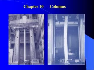
Columns
10. Columns. Presented by: Dr. Mohammed Arafa. In the design of columns, cross-sectional area is selected such that allowable stress is not exceeded. deformation falls within specifications.

Columns
E N D
Presentation Transcript
10 Columns Presented by:Dr. Mohammed Arafa
In the design of columns, cross-sectional area is selected such that • allowable stress is not exceeded • deformation falls within specifications • After these design calculations, may discover that the column is unstable under loading and that it suddenly becomes sharply curved or buckles. Stability of Structures
Consider model with two rods and torsional spring. After a small perturbation, • Column is stable (tends to return to aligned orientation) if Stability of Structures
Assume that a load P is applied. After a perturbation, the system settles to a new equilibrium configuration at a finite deflection angle. Stability of Structures • Noting that sinq < q , the assumed configuration is only possible if P > Pcr.
Consider an axially loaded beam. After a small perturbation, the system reaches an equilibrium configuration such that • Solution with assumed configuration can only be obtained if Euler’s Formula for Pin-Ended Beams
The value of stress corresponding to the critical load, Euler’s Formula for Pin-Ended Beams • Preceding analysis is limited to centric loadings.
A column with one fixed and one free end, will behave as the upper-half of a pin-connected column. • The critical loading is calculated from Euler’s formula, Extension of Euler’s Formula
Sample Problem 10.1 An aluminum column of length L and rectangular cross-section has a fixed end at B and supports a centric load at A. Two smooth and rounded fixed plates restrain end A from moving in one of the vertical planes of symmetry but allow it to move in the other plane. • Determine the ratio a/b of the two sides of the cross-section corresponding to the most efficient design against buckling. • Design the most efficient cross-section for the column. L = 20 in. E = 10.1 x 10⁶ psi P = 5 kips FS = 2.5
SOLUTION: The most efficient design occurs when the resistance to buckling is equal in both planes of symmetry. This occurs when the slenderness ratios are equal. • Buckling in xy Plane: • Most efficient design: • Buckling in xz Plane: Sample Problem 10.1
Sample Problem 10.1 • Design: L = 20 in. E = 10.1 x 10⁶ psi P = 5 kips FS = 2.5 a/b = 0.35
Eccentric loading is equivalent to a centric load and a couple. • The deflection become infinite when P = Pcr • Maximum stress Eccentric Loading; The Secant Formula • Bending occurs for any nonzero eccentricity. Question of buckling becomes whether the resulting deflection is excessive.
Sample Problem 10.2 The uniform column consists of an 8-ft section of structural tubing having the cross-section shown. • Using Euler’s formula and a factor of safety of two, determine the allowable centric load for the column and the corresponding normal stress. • Assuming that the allowable load, found in part a, is applied at a point 0.75 in. from the geometric axis of the column, determine the horizontal deflection of the top of the column and the maximum normal stress in the column.
SOLUTION: • Maximum allowable centric load: - Effective length, - Critical load, - Allowable load, Sample Problem 10.2
Eccentric load: - End deflection, - Maximum normal stress, Sample Problem 10.2
Previous analyses assumed stresses below the proportional limit and initially straight, homogeneous columns Design of Columns Under Centric Load • Experimental data demonstrate • for large Le/r, scr follows Euler’s formula and depends upon E but not sY. • for small Le/r, scr is determined by the yield strength sY and not E. • for intermediate Le/r, scr depends on both sY and E.
For Le/r > Cc Structural Steel American Inst. of Steel Construction • For Le/r > Cc • At Le/r = Cc Design of Columns Under Centric Load
Alloy 6061-T6Le/r < 66: Le/r> 66: • Alloy 2014-T6Le/r < 55: Le/r> 66: Design of Columns Under Centric Load Aluminum Aluminum Association, Inc.
Sample Problem 10.4 • SOLUTION: • With the diameter unknown, the slenderness ration can not be evaluated. Must make an assumption on which slenderness ratio regime to utilize. • Calculate required diameter for assumed slenderness ratio regime. • Evaluate slenderness ratio and verify initial assumption. Repeat if necessary. Using the aluminum alloy2014-T6, determine the smallest diameter rod which can be used to support the centric load P = 60 kN if a) L = 750 mm, b) L = 300 mm
For L = 750 mm, assume L/r > 55 • Determine cylinder radius: • Check slenderness ratio assumption: assumption was correct Sample Problem 10.4
For L = 300 mm, assume L/r < 55 • Determine cylinder radius: • Check slenderness ratio assumption: assumption was correct Sample Problem 10.4
Normal stresses can be found from superposing the stresses due to the centric load and couple, • Allowable stress method: • Interaction method: Design of Columns Under an Eccentric Load • An eccentric load P can be replaced by a centric load P and a couple M = Pe.