

SlideServe
Menu
Préférences
© SlideServe · v2026

Beam-Columns

gafna avatar
32 diapositives · 832 Views · Aug 20, 2014

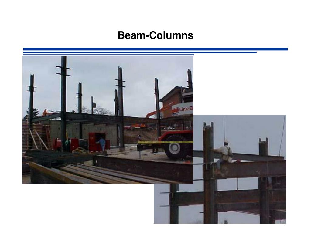
Beam-Columns. A. B. P 1. C. D. P 2. E. F. Members Under Combined Forces. Most beams and columns are subjected to some degree of both bending and axial load. e.g. Statically Indeterminate Structures. Interaction Formula. REQUIRED CAPACITY P r P c
Beam-Columns - slide 1
01 / 32Beam-Columns
1 / 17

Télécharger la présentation

Beam-Columns
Une image / un lien ci-dessous est fourni (tel quel) pour télécharger la présentation

Politique de téléchargement : le contenu du site vous est fourni TEL QUEL pour votre information et votre usage personnel ; il ne peut être vendu, concédé sous licence ni partagé sur d’autres sites sans l’accord de son auteur.Le contenu vous est fourni TEL QUEL, pour votre information et votre usage personnel uniquement. Téléchargez la présentation en cliquant sur ce lien. Lors du téléchargement, si vous ne parvenez pas à télécharger une présentation, l’éditeur a peut-être supprimé le fichier de son serveur.Pendant le téléchargement, si vous ne parvenez pas à obtenir une présentation, le fichier a peut-être été supprimé par l’éditeur.

F I N

Plus de contenu associé

Transcription de la présentation
  1. Beam-Columns

  2. A B P1 C D P2 E F Members Under Combined Forces Most beams and columns are subjected to some degree of both bending and axial load e.g. Statically Indeterminate Structures

  3. Interaction Formula REQUIRED CAPACITY Pr Pc Mrx Mcx Mry Mcy

  4. Axial Capacity Pc

  5. Axial Capacity Pc Elastic Buckling Stress corresponding to the controlling mode of failure (flexural, torsional or flexural torsional) Fe: Theory of Elastic Stability (Timoshenko & Gere 1961) Flexural Buckling Torsional Buckling 2-axis of symmetry Flexural Torsional Buckling 1 axis of symmetry Flexural Torsional Buckling No axis of symmetry AISC Eqtn E4-4 AISC Eqtn E4-5 AISC Eqtn E4-6

  6. Axial Capacity Pc LRFD

  7. Axial Capacity Pc ASD

  8. Moment Capacities

  9. Moment Capacity Mcx or Mcy REMEMBER TO CHECK FOR NON-COMPACT SHAPES

  10. Moment Capacity Mcx or Mcy REMEMBER TO ACCOUNT FOR LOCAL BUCKLING IF APPROPRIATE

  11. Moment Capacity Mcx or Mcy LRFD ASD

  12. Axial Demand

  13. Axial Demand Pr LRFD ASD factored service

  14. Demand

  15. P y M Second Order Effects & Moment Amplification P W ymax @ x=L/2 = d Mmax @ x=L/2 = Mo + Pd = wL2/8 + Pd additional moment causes additional deflection

  16. additional moment causes additional deflection Second Order Effects & Moment Amplification Consider Mmax = Mo + PD

  17. Design Codes AISC Permits Second Order Analysis or Moment Amplification Method Compute moments from 1st order analysis Multiply by amplification factor

  18. Braced vs. Unbraced Frames Eq. C2-1a

  19. Braced vs. Unbraced Frames Eq. C2-1a Mnt = Maximum 1st order moment assuming no sidesway occurs Mlt = Maximum 1st order moment caused by sidesway B1 = Amplification factor for moments in member with no sidesway B2 = Amplification factor for moments in member resulting from sidesway

  20. Braced Frames Pr = required axial compressive strength = Pu for LRFD = Pa for ASD Pr has a contribution from the PD effect and is given by

  21. Braced Frames a = 1 for LRFD = 1.6 for ASD

  22. Braced Frames Cm coefficient accounts for the shape of the moment diagram

  23. Braced Frames Cm For Braced & NO TRANSVERSE LOADS M1: Absolute smallest End Moment M2: Absolute largest End Moment

  24. Braced Frames Cm For Braced & NO TRANSVERSE LOADS COSERVATIVELY Cm= 1

  25. Unbraced Frames Eq. C2-1a Mnt = Maximum 1st order moment assuming no sidesway occurs Mlt = Maximum 1st order moment caused by sidesway B1 = Amplification factor for moments in member with no sidesway B2 = Amplification factor for moments in member resulting from sidesway

  26. Unbraced Frames

  27. Unbraced Frames

  28. Unbraced Frames a = 1.00 for LRFD = 1.60 for ASD = sum of required load capacities for all columns in the story under consideration = sum of the Euler loads for all columns in the story under consideration

  29. Unbraced Frames Used when shape is known e.g. check of adequacy Used when shape is NOT known e.g. design of members

  30. Unbraced Frames I = Moment of inertia about axis of bending K2 = Unbraced length factor corresponding to the unbraced condition L = Story Height Rm = 0.85 for unbraced frames DH = drift of story under consideration SH = sum of all horizontal forces causing DH

  31. Homework • 6.2-1 • 6.2-2 • 6.5-2 • 6.5-6 • 6.6-1