Download
1 / 23
230 likes | 446 Vues
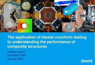
The application of biaxial cruciform testing to understanding the performance of composite structures. Caroline Jones CompTest 2003 January 2003. Summary.

E N D
The application of biaxial cruciform testing to understanding the performance of composite structures Caroline Jones CompTest 2003 January 2003
Summary This presentation highlights recent developments in the field of biaxial cruciform testing and discusses how the benefits from these experimental programmes are being used to optimise composite structures and reduce the duration of the certification process.
Contents 1 Development of the biaxial cruciform test 2 The biaxial test • Experimental arrangement 3 Using biaxial cruciform test data • Failure criteria development • Numerical modelling tools 4 Conclusions 5 Any Questions?
Specimen Design • Cruciform specimen design • GRP cladding • Aluminium end tabs • adhesive with low residual stress post-cure • Test area 90mm-120mm • Honeycomb, sandwich panels, structures, through thickness reinforcement
The biaxial test machine • Four primary actuators • 500kN/1500kN loads • Two secondary actuators • bolt hole loading • Grip system • Safety
Section 2 The biaxial test
Experimental Arrangement • orientation • loading ratios/testing ratios • calibration • performance envelope • failure strength • use of anti-buckle guide • hot/wet testing X, 0° Y, 90°
Use of the bolt hole loading rig Y, 90°, Fy=-0.7 X, 0°, Fx=+1.0 • Open hole • Filled hole • Loaded hole N.B. Load on bolt is 12kN
Using biaxial cruciform data Section 3
Uniaxial or biaxial? • Biaxial • more expensive per test • minimal experimental scatter • several results per test • smaller test programme • less time consuming • boundary conditions representative • Uniaxial • less expensive per test • high experimental scatter • one result per test • large test programme • time consuming • boundary conditions unrepresentative
Development of failure criteria Development of structural concepts More realistic representation of a structure in service – leading to more efficient designs Development of novel materials Development of modelling tools How is the data being used?
Development of performance and failure criteria • Use failure strength to test and develop biaxial failure criteria • Use performance envelope to confirm predictions
Development of Numerical Modelling tools • Bolted joint structures • Coupled global-local modeling tools • Open holes • Loaded fasteners
Global-local analysis (1) 1. Create global model (ABAQUS)(arbitrary curvature and mesh) 2. Run Q_global_bolt to add bolts &foundations 3. Run updated global model (ABAQUS)
Global-local analysis (2) 4. Use Q_global_local to create local models 5. Run local models 6. Run Q_predict for multi-axial strength prediction with bolt load
Conclusions Section 4
Conclusions • Boundary conditions representative of those found in structures make the data obtained from biaxial cruciform tests extremely valuable. • Direct benefits being derived from biaxial cruciform test work include the development of performance and failure criteria and numerical modeling tools used to analyse complex composite bolted structures. • Recent developments made in biaxial cruciform testing represent major steps in understanding materials and their use in structural design
Any Questions? Section 5
Instrumentation • Shadow moiré • Photoelasticity • Thermoelasticity • NDE (ANDSCAN) • Video strain mapping • Combined thermo/photoelasticity
Sensitivity to delamination growth Photoelastic coatings are used to obtain both the optical and thermal data High operational strains require multiple coatings to monitor both global and local delamination fronts
Thermal monitoring of loading sequence Deltatherm image (200 f/sec) of specimen surface loaded to 6000me/-3000 me