Download
1 / 46
530 likes | 777 Vues
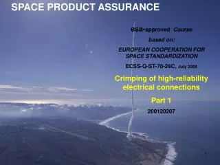
SPACE PRODUCT ASSURANCE. esa- approved Course based on: EUROPEAN COOPERATION FOR SPACE STANDARDIZATION ECSS-Q-ST-70-26C, July 2008 Crimping of high-reliability electrical connections Part 1 200120207. Change Log. 1. Scope. 1. Scope. 3 Terms, definitions and abbreviated terms.

E N D
SPACE PRODUCT ASSURANCE esa-approved Course based on: EUROPEAN COOPERATION FOR SPACE STANDARDIZATION ECSS-Q-ST-70-26C, July 2008 Crimping of high-reliability electrical connections Part 1 200120207
5.1 Preparatory conditions 2010 Changed to AS22520 (SAE Std replacing MIL Std)
5.2 Crimping operations for specific interconnections 5.2.1 General
5.2 Crimping operations for specific interconnections 5.2.1 General (continued)
Dispersive Crimp tool M22520/2-01 (AFM8)for AWG 20-32 [M22520/1-01 (AF8) is larger Daniels tool for AWG 12-26] With positioner removed With positioner fitted
Daniels Tooling Guide • http://www.dmctools.com/_pdf/Catalogs/ConnectorToolingGuide.pdf • Pages 6 & 7 describe the M22520/1-01 (AF8) tool for AWG12 - 26 • Pages 8 & 9 describe the M22520/2-01, (AFM8) tool for AWG 20 - 32 • Page 17 shows contact part numbers and wire ranges. • Page 17 also shows the tools (AF8 and AFM8) and the accessories required. • contacts shown on pages 17 - 28 which are in the range • AWG 12 - 26 will be compatible with the AF8 tool • contacts shown on pages 17 - 28 which are in the range • AWG 20 - 32 will be compatible with the AFM8 tool
Compactive & Dispersive Crimp tools AMP tool for 3 different wire size ranges 21
5.2 Crimping operations for specific interconnections 5.2.2 Material Selection https://escies.org/download/specdraftapppub?id=117
5.2 Crimping operations for specific interconnections 5.2.2 Material Selection(continued)
lug terminals Before crimping After crimping Crimp over back side (incorrect)
lug terminals Insulatedconnectors are colour coded and may also be dot coded: AWG#26 to 22: yellow 1 dot AWG#24 to 20: white 2 dots AWG#22 to 18: red 1 dot AWG#16 to 14: blue 2 dots AWG#12 to 10: yellow 1 dot
Butt (in-line or end-to-end) splice Butt Splice (weld side) Butt Splice (end view) Butt Splice (back side) Crimp over weld (correct) Butt splices are used to dress and terminate multiple conductors of the same or different gauges in an end-to-end or series configuration.
Through (stub or parallel) splice Crimp over weld (correct)
NASA Workmanship Inspectors Pictorial Reference Visit: http://workmanship.nasa.gov/lib/insp/2%20books/frameset.html Daniels Crimping Glossary Visit: https://www.dmctools.com/Catalog/glossary.htm
BIN Coding of crimp terminals BIN: Basic Identification Number used by most crimp terminal manufacturers Generally shown as a number of coloured bands or spots on the crimp terminal. Identifies the wire acceptance size of the terminal, 10-12, 16-18, 20-22, 24-26, etc. Not every company employs all three numbers, eg one company uses one red band to identify a 20-22 terminal. BIN coding follows the international colour code used for resistor values and wire numbering: 0 Black 5 Green 1 Brown 6 Blue 2 Red 7 Violet 3 Orange 8 Grey 4 Yellow 9 White.
5.2 Crimping operations for specific interconnections 5.2.3 Process Review and documentation
5.2 Crimping operations for specific interconnections 5.2.4 Connector barrel and single wire crimping 37
5.2 Crimping operations for specific interconnections 5.2.4 Connector barrel and single wire crimping (continued) Acceptable Acceptable Defect 38
5.2 Crimping operations for specific interconnections 5.2.4 Connector barrel and single wire crimping (continued)
5.2 Crimping operations for specific interconnections 5.2.5 Connector barrel and multiple wire crimping In fact, 1 AWG 24 + 1 AWG 22 gives a closer approximation to AWG 20 cross sectional area.
5.2 Crimping operations for specific interconnections 5.2.5 Connector barrel and multiple wire crimping (continued) For example, not a combination of pure copper and high-strength copper alloy 41
5.2 Crimping operations for specific interconnections 5.2.5 Connector barrel and multiple wire crimping (continued) For example, for an AWG22 wire (axial strength requirement 60N) plus an AWG20 wire (axial strength requirement 90N), the combined axial-strength requirement would be 0.75 x (60+90) = 112.5N This would be the minimum required tensile strength for the crimp when the wires are twisted together. 42
5.2 Crimping operations for specific interconnections 5.2.5 Connector barrel and multiple wire crimping (continued) 43
5.2 Crimping operations for specific interconnections 5.2.5 Connector barrel and multiple wire crimping (continued)
5.2 Crimping operations for specific interconnections 5.2.6 Ferrule shield crimping