Vapor Compression Cooling (VCC) in Electronics
550 likes | 859 Vues
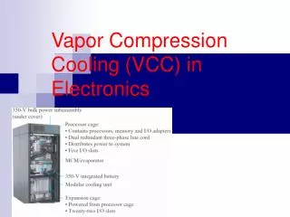
Vapor Compression Cooling (VCC) in Electronics. Outline. Benefits Disadvantages History Basic operation Engineering Design Cold plate Refrigerants Capillary tube Condensation Product Reliability Current applications: Supercomputer and Mainframe Cooling Current research:

Vapor Compression Cooling (VCC) in Electronics
E N D
Presentation Transcript
Outline • Benefits • Disadvantages • History • Basic operation • Engineering Design • Cold plate • Refrigerants • Capillary tube • Condensation • Product Reliability • Current applications: • Supercomputer and Mainframe Cooling • Current research: • Microscale VCRS
Benefits • Allows cooling to below ambient temperatures, increasing performance, reliability, and allowing operation in higher temperatures. • High COP (around 2 to 3). • Ability to remove very large heat loads. • Widely available; compressor and fan only moving parts, stable, and reliable. (moran, 2001). • Low mass flow rate of refrigerant needed. • Ability to transport heat away from its source. • COP up to 3 times greater than thermoelectric coolers or more. (peeples, 2001)
Benefits • Sub ambient temperature operation allows CMOS (complementary-symmetry/metal-oxide semiconductor) transistors to switch on and off faster (peeples, 2001). • CMOS circuits are a major class of integrated circuit and include microprocessors, microcontrollers, and other digital logic circuits (Wikipedia, http://en.wikipedia.org/wiki/CMOS) .
Benefits • The following physical parameters favor low temperature operation: carrier mobility, and junction leakage. • Although at low temperatures there is an increase in the failure rates due to hot carriers, overall failure rates decrease at lower temps due to the overall increased characteristics mentioned previously (Moran,2001). • Definitions: • Carrier mobility- velocity of charge carriers in a solid material with an electric field applied to it(Wikipedia, http://en.wikipedia.org/wiki/Electron_mobility). • Hot carriers- high energy carriers (Moran,2001). • Junction leakage-undesirable conductive paths in certain components, for instance, in capacitors. Also, a pathway through which electric discharge may slowly take place (IEEE Standard Dictionary of Electrical and Electronics Terms).
Benefits • Much like heat pipes, vapor compression coolers use the high heat of vaporizations of the working liquid to remove large amounts of heat. • Therefore, low mass flow rates required. • Advantage over a chilled liquid loop that requires a much higher mass flow rate. • Much like heat pipes, VCCs use the high heat of vaporization of liquids to transport large amounts of heat, thus low amounts of liquid are required. However, in chilled liquid loop coolers, the liquid is heated but not necessarily evaporated. (Cengel and Boles, 2002)
Disadvantages • The cost of employing the cooling system may be 10-20% of the cost of the entire system. • Large space and input power. • The disadvantages of the cooling system has to be weighed with the large advantages. A lot of times, traditional methods of cooling like air cooling is not feasible so a VCC is required. • However, if the cooling requirements can be satisfied with traditional techniques, the traditional technique are the preferred cooling method (Moran, 2001).
History • The vapor compression refrigerator was first proposed in 1805 and a model was constructed in 1834. • Vapor compression technology is well established but only recently used in electronics cooling. • Kryotech was one of the first companies to employ the technology. • By the late 90’s companies like AMD, Sun Microsystems, IBM, and SYS Technologies had all used Vapor Compression cooling. (Schmidt et al., 2002)
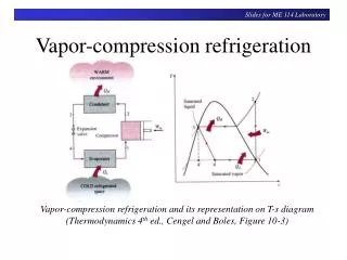
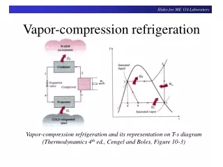
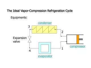
Basic Operation (Peeples,2001)
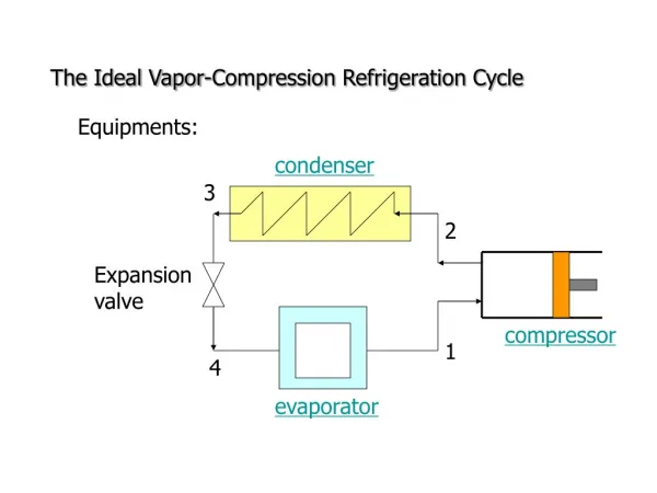
Basic Operation • Ideal cycle • 1-2 The working refrigerant, a saturated vapor, is carried through the suction tube to the compressor. The compressor compresses the saturated vapor into a superheated vapor which is then passed to the condenser. • 2-3 The heat of the hot and high pressure vapor is released into the environment from the condenser. The working gas is transformed into a saturated liquid. • 3-4 The liquid is pumped through a capillary tube or a thermal expansion valve into the evaporator, dropping significantly in temperature. The working fluid is a saturated mixture. • 4-1 Heat flows into the evaporator from the heat source. The heat vaporizes all the working liquid (refrigerant), at the end of this stage the vapor is saturated, and the process repeats. (Peeples,2001)
Qout = QH Win Qin = QL Basic Operation • Qout, QH denotes the heat released to the environment. • Qin, QL denote heat absorbed from the refrigerated space. • 2 represents the actual position of the state. 2s represents the position of the state if it were irreversible. • In the ideal case: • 12 isentropic (s=const) • 23 isobaric (P=const) • 34 isenthalpic (h=const) • 41 isobaric ( P=const) (Peeples,2001)
Basic Operation • The heat absorbed by the evaporator (Qin) released from the condenser (Qout), and actual and isentropic work input by the compressor can be determined from the equations: • The efficiency of the compressor is given by: Where h is the enthalpy at various states, the subscripts s and a refer to isentropic and actual, and w refers to work. (Cengel and Boles, 2002)
Basic Operation • Actual cycle • The deviation of the ideal cycle to the actual cylce is due to irreversibilities; mainly due to fluid friction-causing pressure drops and heat transfer to the system or the environment. • In the ideal cycle the state of the refrigerant is precisely know, for example, at stage 1 the refrigerant is a saturated vapor. However, in actuality the state of the refrigerant may not be precisely known and is usually a superheated vapor. (Cengel and Boles, 2002)
Basic Operation Note that the pressure drops between stages 8-1, 2-3,4-5 etc. cause alterations to the TS diagram. The process 1-2’ represents a compression path that may be more desirable than the 1- 2 pathway because the specific volume of the refrigerant is lower and thus the work input is lower. (Cengel and Boles, 2002)
Basic Operation (Cengel and Boles, 2002)
Basic Operation • The Coefficient of performance of the VCR is the ratio of heat into the evaporator to work put into the compressor. Generally, the COP is around 2 to 3. • The COP can be determined by finding the ratio of the enthalpies between the throttling valve and evaporator and between the evaporator and the compressor. (Cengel and Boles, 2002)
Basic Operation • The most efficient refrigeration cycle is that of a Carnot refrigerator. • The coefficient of performance of the Carnot refrigerator gives the maximum performance between two hot and and cold temperatures. • This value can be compared to the actual COP to determine how close to ideal the refrigerator is operating. • Note that the Carnot cycle is a reversible cycle. Reversible cycles are cycles that do not generate any entropy due to friction, heat transfer, etc. For a reversible cycle: (Cengel and Boles, 2002)
Basic Operation • The coefficient of performance for a Carnot cycle is: • Note: the COP increases as the ratio of TH/TL decreases. Therefore, we want TH and TL to be as close as possible. Usually, TL is specified and TH can be altered. The reason for TH/ TL affecting COP is that for a given TL the greater the TH the greater the amount of work input, decreasing COP. (Cengel and Boles, 2002)
Basic Operation • The area enclosed in the TS diagram generally describes the net heat transfer and the work of the system. For refrigeration, work input lowers the COP for a given heat rejection; therefore, altering the states of the cycle to get a smaller enclosed area will increase performance. (Cengel and Boles, 2002)
Engineering Goals • The design of a cost-effective and efficient VCC involves the following considerations: • Cold surfaces can not be allowed to collect condensate from the air. • The most suitable refrigerant for the given application, as well as the tubing to supply and remove the refrigerant, must be chosen. • Compressor and condenser design. • The cold plate must efficiently lift heat from the device to be cooled. (Peeples,2001)
Cold Plate/Evaporator • The cold plate (evaporator) is a heat exchange device which transfers heat from the heat source to the working fluid. • Cold plate design must assure efficient heat transfer from the device being cooled to the refrigerant inside the cold plate. • The cold plate must be fabricated from thin and thermally conductive material to minimize thermal resistance while maintaining structural stability. • The mating surface between the cold plate and the heated body must be flat and smooth to minimize contact resistance. (Peeples,2001)
Refrigerant Fluids • The refrigerant’s physical properties determine its evaporating temperature at a specified operating temperature, as well as, its capacity to transport heat. • The well known refrigerants R-134a and R-404a (and others) perform well for cooling high power electronics due to their high heat transport characteristics, low possibility of environmental harm, corrosion, and risk of explosion. (Peeples,2001)
Refrigerant Fluids • When making a decision as to which refrigerant to use and under what pressures to operate the VCR, consideration of the refrigerant’s temperature of vaporization and condensation should be considered. If the temperature of the refrigerant doesn’t reach the vaporization point (at the operating pressure) the VCR will not work properly. To ensure a proper heat transfer rate a 5 to 10 degree Celsius temperature difference should be maintained between the evaporator and the condenser with the refrigerant. • The next slide shows the P-T curves of R-404a and R-134a describing the refrigerant’s lowest practical operating limit. (Peeples,2001)
Refrigerant Fluid Saturation Pressure and Temperature (Peeples,2001)
Capillary Tube • The capillary tube has the function of transporting the working liquid from the condenser to the evaporator. • The small diameter and long length of the tube produces a large pressure drop. • Refrigerants chosen have a large Joule-Thomson coefficient, which tells us how much the temperature drops as the pressure drops at constant enthalpy. • Since pressure drops create performance losses careful design must be taken so that the tube lengths and diameters are minimal. (Heydari, 2002)
Condensation • Condensation, much like in TEC, is a problem because the surfaces of the VCR may be lower than the dew point. • Since water is hazardous to electronic assemblies, condensation must be minimized by insulating surfaces from air in spot-cooling applications. (Peeples,2001) • More on sealants later on in the slides.
Product Reliability • Electro-mechanical systems generally have product life cycles called “bathtub curves”. • The curve has three distinct regions • Infant mortality- rate of failure decreases with time • Normal use-rate of failure relatively constant • Wear out- rate of failure increases with time. (Peeples,2001)
Improving Performance • In some applications the heat rejection demands (efficiency or amount) are higher than what can be handled by a vapor compression cycle running on a regular cycle. In these cases, modifications of the cycle must occur. • Like previously mentioned, modifying the TH/TL to get them as as low as possible will increase performance but larger modifications may need to be made. (Cengel and Boles, 2002)
Improving Performance • An example is a cascade cycle, which performs the refrigeration process in two cycles that are in series. This is useful in situations (industrial), where there is a large temperature difference between the hot and cold side for one cycle to be practical. • If the fluid used in the cascade system is the same, the heat exchanger can be replaced by a mixing chamber, known as a flash chamber which has better heat transfer characteristics. (Cengel and Boles, 2002)
Cascade Refrigeration (Cengel and Boles, 2002)
Refrigeration System w/ Flash Chamber (Cengel and Boles, 2002)
Supercomputer and Mainframe Cooling • The extremely high cooling demands of mainframes and supercomputers are ideal applications for VCRs because other cooling systems can not provide the necessary cooling capacity. An example of is IBM’s G4 mainframe (shown on the next slide) (Schmidt et al.,2002)
Supercomputer and Mainframe Cooling (Schmidt et al.,2002)
Supercomputer and Mainframe Cooling • The bulk power assembly at the top provides 250 volts dc to the mainframe. • Below the bulk power is the central electronic complex where the MCM (multichip module) is located. The MCM housing the 12 processors.
Supercomputer and Mainframe Cooling • Below the MCM are blowers that provide air cooling for all of the components in the processors except for the processor module, which is cooled by refrigeration. • Below the blowers are two modular refrigeration units (MRUs-the VCR) which provide cooling via the evaporator mounted on the processor module. • In the bottom of the mainframe are the input/ output (I/O)connections and two blowers. The blowers cool the I/O connections, as well as, provide the cooling for the condenser of the MRUs. (Schmidt et al.,2002)
Multichip Module (MCM) • The mainframe’s processing unit, MCM, is constructed as follows. • Note the evaporator above the chips. (Schmidt et al.,2002)
Modular Refrigeration Unit (MRU) • The MRU (VCR) houses all the refrigeration components except the evaporator. The MRU contains the: • Condenser • Thermostatic expansion valve • DC rotary compressor (Schmidt et al.,2002)
Condensation Protection • To avoid moisture condensation on the MCM hardware, all the cooling hardware including the evaporator copper cold plate is contained in an airtight metal enclosure with one open face. • 260 grams of silica gel desiccant is kept there to absorb any moisture leaking into the enclosure. (Schmidt et al.,2002)
Condensation Protection • The figure on the previous slide also shows a flat board that replaced the planar board in order to test the effectiveness of various sealants in keeping moisture out of the evaporator cavity. • The results show that the Butyl #1 rubber sealant displayed the best sealant characteristics, allowing the least amount of humidity to enter. (Schmidt et al.,2002)
Microscale VCRs • To utilize VCRs in laptops, personal computers, or other cooling applications of small size, the VCR size must be reduced to fit within a small enclosure. The next section discusses progression in this area. • Since miniature VCRs have high heat loads to transfer away, the condenser and evaporator must be designed such that they transfer enough heat to satisfy the heat removal demands. • The most difficult part in designing a miniature VCR is the compressor.
Microscale Evaporators • Chirac et al. (2005) suggest using an evaporator with microchannels through the center as an option to miniaturize the evaporator. The microchannels transfer large amounts of heat reducing the evaporator size needed to transfer the heat load from the heat source.
Microscale Condenser • Chiriac et al. also describe a condenser with microchannels through the center. A heat sink surrounds the outside of the condenser while a fan blows air over the heat sink.
Refrigerant Fluids • Heydari (2002) performed a simulation with a miniature VCR which included a miniature compressor to cool a computer system. • The figure shows ammonia has the highest COP relative to the other refrigerants. However, when the refrigerant’s cost, environmental impact (ozone depletion and global warming potential), and safety issues were considered, Heydari concluded the optimal refrigerant to use is R134a.
Condenser Temperature and Performance • Heydari found that with the computer chip junction temperature and heat absorbed by the evaporator fixed, decreasing the condenser temperature decreases the COP.
Evaporator Temperature and Performance • Lastly, Heydari found that for a fixed junction temperature and the amount of heat absorbed by the evaporator fixed, increasing the evaporator temperature increases the COP; but the amount of heat condensed decreases.
Refrigerant Fluids • When it comes to the performance of refrigerants in miniature VCRs, Phelan et. Al. (2004) performed experimental analysis comparing three refrigerants: ammonia, R-134a, and R-22 to determine which of the three produce the highest COP for a miniature VCR under various conditions. • The factors tested were the evaporator and condenser temperatures, as well as, the efficiency of the compressor which was predicted to decrease as the size of the compressor decreased. The results are shown on the next slide.
Refrigerant Fluids Phelan et. Al. (2004)
Refrigerant Fluids • For each condition, ammonia has the highest COP. • The higher COP values are due to ammonia’s greater latent heat of vaporization. • However, due to ammonia’s greater adverse environmental and physiological effects, R-134a is more predominantly used. • Ammonia is typically used only with a secondary loop due to its toxicity. (Phelan et. al 2004)
Microscale VCRs • Utilizing VCRs for electronics cooling applications has been limited by their large size due to the use of traditional components like pistons, linkages and pressure vessels. • University of Illinois has a DARPA grant to develop miniature VCR’s for use with cooled military uniforms for use in desert warfare. This Technology could also be used for electronics applications. However, the miniature compressor has been difficult to achieve. • Research is ongoing on a Stirling cycle MEMS cooler being developed in NASA Glenn. (Moran,2001)
Microscale VCRs • The Stirling Cycle is much like the vapor compression cycle and is shown below. (Moran,2001)