Download
1 / 29
290 likes | 486 Vues
GOSSIPO-3: Measurements on the Prototype of a Read-Out Pixel Chip for Micro-Pattern Gas Detectors. André Kruth 1 , Christoph Brezina 1 , Sinan Celik 2 , Vladimir Gromov 2 , Ruud Kluit 2 , Francesco Zappon 2 , Klaus Desch 1 , Harry van der Graaf 2

E N D
GOSSIPO-3: Measurements on the Prototype of a Read-Out Pixel Chip for Micro-Pattern Gas Detectors André Kruth1, ChristophBrezina1,Sinan Celik2, Vladimir Gromov2, Ruud Kluit2, Francesco Zappon2, Klaus Desch1, Harry van der Graaf2 1Physics Department, University of Bonn, Nussallee 12, 53115 Bonn, Germany 2National Institute for Subatomic Physics (Nikhef), Science Park 105, 1098 XG Amsterdam, The Netherlands TWEPP, Aachen September 20th-24th 2010
Outline • Read-Out of Ingrid-Gaseous Detectors • GOSSIPO-3: Features & Architecture • Measurement Results & Discussion • Summary & Outlook
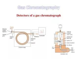
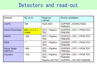
Read-Out of Ingrid-Gaseous Detectors Cathode (Drift) Plane Cluster1 1mm …1m → Drift Gap Cluster2 Gas Amplification Structure Cluster3 400V 50mm Avalanche Gap Read-Out Chip CPAR Front-End Circuit Gas-avalanche detector combining a gas layer as signal generator with a CMOS readout pixel array • Particle track image (projection) with 3D track reconstruction • No sensor leakage current compensation • Low parasitic capacitance (less than 10fF) • Single-electron efficiency by high gas gain • Micro-discharges in avalanche gap • Time (z-) resolution set by longitudinal diffusion
GOSSIPO-3 Features Small prototype for a read-out chip for MPGDs IBM 130nm CMOS (8 metal layers) 60mm x 60mm pixels (high granularity) ToA Measurement and ToT Measurement [Charge] Local TDC in every pixel Design Goals: 3mW per channel Arrival time measurement up to 102ms Arrival time accuracy 1.6ns (one fast VCO bin) ToT accuracy 200e- accuracy (<50ns)
Common-Stop Timing Scheme Fast clock: 640MHz (1.6ns time bins), started by discriminator Slow clock: 40MHz (25ns time bins), absolute external timing
GOSSIPO-3 Architecture 3 Front-Ends (preamp, comp) Pixel (pre-amplifier, comp, Threshold DAC, high resolution TDC (VCO), counters & control logic) 2 LDOs (generate controllable Power Supply Voltage of Ring Oscillators) 2mm 1mm Ingrid preamp Bias generating circuit
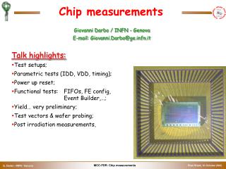
Demonstrator Test Set-Up Power Regulators -=G3=- Demonstrator SRAM USB Port FPGA mC External Bias Overwrite S3 Multi IO Board (general purpose test board designed by Bonn group) G3 Test Board (dedicated PCB)
Front-End Performance Pre-Amplifier with MOSFET feedback parasitic capacitance CFB about 1fF – high gain Low parasitic input capacitance
Front-End Performance Excellent pre-amplifier noise performance Charge injection through test pad Measurement includes output pad driver Measured and simulated sNOISE ~ 4mV => ENC ~ 25e- Simulation QIN=375e- Measurement Measurement (averaged) DV=64mV VPK-PK<20mV
Front-End Performance Pre-amplifer measurement for different channels Metal-Metal Injection Capacitance CTEST~1fF Stable high gain Varying time constant of feedback discharge Chip#1 UIN●CTEST1/CFB1 Chip#2 UIN●CTEST2/CFB2 Chip#3 UIN●CTEST3/CFB3 CTEST and CFB are well reproducible
Front-End Performance ToT measurement for different channels QIN=375e- ToT channel to channel mismatch up to 50% w/o offline calibration Jitter on TOT trailing edge caused by noise on pre-amplifier signal trailing edge Cross-talk between channels observed when pad driver switches Channel#1 ToT1 Channel#2 ToT2 Channel#3 ToT3
Analysis of time variation of the feedback discharge Process variation of small feedback MOSFET responsible for variation of feedback current Small feedback MOS needed for high gain Front-End Performance
Front-End Performance Internal delay [including pad drivers] due to time walk 6ns asymptotical delay for a charge >6000e- Delay injection to comperator >1.6ns TDC bin Further reduction of delay saves offline calibration
LDO controls supply voltage of fast TDC ring-oscillator (arrival time measurement) Oscillation frequency of f=640MHz in all process corners Time bin size T=1.56ns Maximum run time 25ns (16 bins) VOUT_LDO=0.61V (fast corner)..1.10V (slow corner) Occupancy expectation gives avg. DIOUT_LDO=24mA peak DIOUT_LDO=44mA VCO control characteristic allows formax. DVLDO_OUT=31mV for 25ns LDO Performance
LDO Performance Step response to typical load step of 20mA Load externally connected Inductance of package and bond wires limits response time
LDO Performance Settling time to nominal VOUT value for different (external) load steps
TDC Performance Counting steps of TDC (input signal directly at digital logic)
Pixel Performance Counting steps of TDC (input signal at analog input)
Summary • Successful operation and measurements: • Front-End: • Internal delay limited by pad drivers • Source of pixel to pixel TOT mismatch identified • High gain / low noise • LDOs: • Step response time critical for TDC performance • Close match between simulation and measurement • TDC: • Transition region of counting steps ~25% of TDC bin (wc) • Bin size / fast oscillator frequency reproducible for multiple channels and chips • Gossipo-3 design team joins Timepix II design efforts • Timepix II will benefit from lessons learned
Pre-Amplifier Schematic Input stage Voltage follower Vdd_ana 720 nA 435 nA 70 nA Uout_preamp C*= 6f Uout_comp Discr. ncap C=170fF gm=23u 5/0.24 UTHR_pixel sub_preamp (0.2V) Preamp_in 1fF Cpar ≈ 10 fF Ron = 30MΩ Ron = 100MΩ Tfb Vdd_ana 0.48/2.4 0.48/2.4 UTHR_common 6 nA 2nA 2.4/2.4 2.4/2.4 Baseline recovery Feedback
Front-End Performance Simulated internal delay [Injection to Comparator Output] based on parasitc extraction
LDO Performance Static ROUT measurement
LDO Performance Linearity measurement
LDO Performance Step response to maximum load step 40mA additional external load inductance of package and bond wires limit response time
GOSSIP vs. TPC GOSSIP Small drift gap (1mm) Track perpendicular to read-out plane TPC Large drift gap (1m) Track parallel to read-out plane
Pixel Electronics Block diagram of the pixel Local fast VCO (640MHz) 4 bit Fast counter Logic: Counters & Control 8 bit ToT counter Preamp Discr. HIT Control pad Oscillator 12 bit Slow counter -Threshold - Mask 60mm Time / Counting Threshold DAC Preamp & Comparator DAC 6 bit Pixel Configuration Memory • Control signals • Clock • TRIGGER (common stop) • TOKEN • RESET 60mm • LFSR = Counters • (data taking) • or • LFSR = Shift registers • (data read-out) Layout of the pixel