Download
1 / 23
230 likes | 339 Vues
Pixel Read-Out architectures for the NA62 GigaTracker. G. Dellacasa (1), A. Cotta Ramusino(3), M. Fiorini(3), P. Jarron(2) J. Kaplon(2), A. Kluge(2), F. Marchetto (1), S. Martoiu (1), E. Martin Albarran (4), G. Mazza (1), F. Osmic (2), P. Riedler(2), A. Rivetti(1) and S. Tiuraniemi(2)

E N D
Pixel Read-Out architectures for the NA62 GigaTracker G. Dellacasa (1), A. Cotta Ramusino(3), M. Fiorini(3), P. Jarron(2) J. Kaplon(2), A. Kluge(2), F. Marchetto (1), S. Martoiu (1), E. Martin Albarran (4), G. Mazza (1), F. Osmic (2), P. Riedler(2), A. Rivetti(1) and S. Tiuraniemi(2) (1) I.N.F.N. Torino (2) CERN (3) I.N.F.N. Ferrara (4) Louvain la Neuve TWEPP 2008 Naxos
Outline • Experiment’s motivations • GigaTracker system overview • Read-out architectures: two possible solutions Giulio Dellacasa
Experiment’s Motivation • Main goal of the experiment is to study the very rare decay K+→π+ ν ν in order to increase the knowledge of the Standard Model • A preliminary measurement has been performed at Brookhaven by AGS E787 and E949 Collaborations (1995-2002). The measured BR, based on 3 events is: BR(K+→π+ ν ν )=1.47+1.3-0.89 x 10⁻¹⁰ • The NA62 experiment aims to collect about 80 events, with a signal to background ratio S/B = 10:1 • The NA62 will use the same cavern (ECN3) at CERN SPS North Area, where now NA48 is located and part of this detector will be reused (liquid krypton e.m. calorimeter LKR) or upgraded Giulio Dellacasa
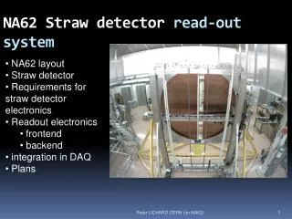
GigaTracker overview • NA62 GigaTracker (GTK) consists of three silicon pixel stations installed over the beam line. It will provide several measurements of the beam particles (K+): timing, direction, momentum • Each station cover an area of 60(X) x 27(Y) mm2.Each pixel 300 μm x 300 μm • The maximum beam particle intensity it will be ~1.5 MHz/mm2 (1 GHz over the whole detector, thus the name GigaTracker) • The required track time resolution is ~ 200 ps (rms) per station (~ 150 ps the whole GTK) and space resolution ~ 100 μm (rms) over the whole system • A material budget of 0.5% X0 is target for each pixel station (sensor thickness : 200 μm, read-out chip thickness : 100 μm) A1÷A4: dipole magnets to provide the momentum selection and recombination Giulio Dellacasa
chip Pixel matrix Mechanical support GigaTracker read-out • Two rows of five readout chips (0.13 μm CMOS technology) are bump bonded to the sensor elements. Each chip reads a matrix of 40x45 pixels • Maximum particle intensity per chip: 130 MHz • Maximum particle intensity per pixel: 140 kHz • Total dose in 1 year: 105 Gy. Thus the system should be cooled at 5 oC or less and GTK stations replaced after a runtime of 60 days under optimum beam conditions • Dissipated heat produced by the 10 readout chips is estimated to be 2 W/cm2 (32 W in total) Giulio Dellacasa
Read-out chip overview • Required data acquisition efficiency is 99%, so circuitry dead time can be an issue • Communications to and from the pixel chip is done via high speed differential signal, to reduce number of connections and system noise • Total average data rate per chip: 4.2 Gb/s (6 Gb/s with fluctuations). To reduce amount of stored data in the chip a triggerless read-out architecture will be adopted • 3 or more high speed serial output depending on their speed • Other I/O pins are foreseen for tests and control purposes Giulio Dellacasa
Time walk correction • With a dynamic range 10:1 and a resolution requirement of 200 ps per station, a time walk compensation has to be applied • Low Power Constant Fraction Discriminator (CFD): analogue signal processing technique • Only one time measurement per hit • Analogue design more complicated • Time Over Threshold (ToT): time walk correction is based on an algorithm derived from the correlation between the ToT (pulse width) and the experienced time walk. • Two time measurements per hit (rising and falling edges) • Accurate calibration of the system is required to define the correction algorithm Giulio Dellacasa
TDC options • In the chip a clock counter will provide a coarse time information. A fine measurement will be obtained with a Time to Digital Converter (TDC) • The dynamic range of the TDC should span 2 clock cycles, to avoid ambiguities • Time to Amplitude Converter (TAC) and Delay Locked Loop (DLL) based TDCs can be developed • A TAC based TDC can be implemented on each pixel • The comparator signal does not need to be propagated outside the pixel • More noise problems inside the cell • Must be designed to be radiation-tolerant (total dose and SEU aspects), due to the high radiation dose received in the pixel area • A DLL based TDC is faster, so it will be used if the TDC will be shared among different pixels • The comparator signal need to be propagated outside the pixel (transmission line problems) • Dead time in case of multiple hits in the same pixels group Giulio Dellacasa
Read-out architectures • Two different architectures for the GTK read-out chip are under development: • Time walk correction using a CFD filter + TDC on pixel based on TAC (On-pixel TDC option) • Time walk correction using ToT technique + TDC based on DLL shared among a group of pixels (End of Column TDC option) • For both architectures the submission of a demonstrator chip is foreseen in the middle of November, in order to evaluate their performance and feasibility for the final read-out option Giulio Dellacasa
On pixel TDC architecture Giulio Dellacasa
The pixel model • CLK: 160 MHz (6.25 ns) • Coarse measure: 10 bit • Fine measure: 7 bit • TDC time binning: 12.5 / 27 ns = 97.6 ps • Derandomization is performed in the pixel cell • Exhaustive simulations have been performed to calculate the correct FIFO depths and to evaluate the impact of the pixel dead time (< 0.2% lost events at 140 kHz ) Giulio Dellacasa
System overview • System Clock 160 MHz • One Course Counter for the whole chip (10 bit) • Each column of 45 pixels is read-out by its own controller (End-of-Column controller) • Only digital buses between pixels and EoC controller • The Matrix controller will merge data coming from m columns (where m depend on the link speed) Giulio Dellacasa
Data Format • End of Column controller will provide data formatting for each column • Data stored in the output buffer (before serializer) are grouped in Frames • Definition of Frame: all the data which belong to the same turn of the Coarse Counter (6,4 μs) • 32 bit per hit: Addresses + Coarse measure + Fine measure • CRC control added in trailer (CRC-16 polynomial is X16+X15+X2+1) Giulio Dellacasa
Existing prototype • The CFD prototype has been done and tested in 2007 • Electrical test: Total time resolution measured 65 ps ÷ 110 ps (depending on the set-up) • Promising results but its performances must be proven after integration in the whole pixel read-out chip and with the detector 3.5 ns shaping 5.5 ns shaping Giulio Dellacasa
On-pixel TDC Demo chip • Prototype submission: middle of November 2008 CMOS 0.13 μm technology • Each pixel cell will be equipped with the whole logic (CFD+TDC) • End of Column controller read-out will be integrated and verified • Exhaustive simulations have been performed to calculate the correct FIFO depths (20) and the data formatting algorithms Giulio Dellacasa
End of column TDC architecture Giulio Dellacasa
Architecture overview • Each pixel cell is equipped with a preamplifier and Time Over Threshold discriminator • ToT output has a constant amplitude and a pulse width proportional to the input charge. It is transmitted to the End-Of-Column circuit • Pulse width is used to correct the time walk • EOC circuit contain all the rest of processing functions: time stamping with the TDC, pixel address encoding, data pipelining and formatting Giulio Dellacasa
1 2 3 4 5 6 7 8 9 10 11 12 . . . 19 20 28 29 36 address TDC 1 32 to 5 bit TDC 2 32 to 5 bit TDC 8 32 to 5 bit TDC 9 32 to 5 bit 5 5 5 5 Architecture overview • Each column is organized in two different bus systems: • Data bus which transmits hit information, leading edge and trailing edge. It consists of 9 coplanar fast transmission lines, each one connected to a group of 5 pixels • A slower 5-bit bus which contains the address of the 9 pixels • Coarse time information is provided by a 6-bit counter hosted in the EoC logic • TDC information (fine time) is encoded in 32-bit words. In order to reduce the among of data to transmit 32 to 5 bit encoders will be used Giulio Dellacasa
TDC architecture • In order to reduce dead time and to reach the efficiency of 99%, the use of a fast TDC is mandatory. So a DLL based TDC will be adopted • Reference clock: 320 MHz (3.125 ns) • DLL consists of 32 delays elements, 100 ps delay each • 2 hit registers (with 5-bit encoder) to provide rising and falling edges of the ToT pulse Giulio Dellacasa
End of Column TDC Demo chip • Prototype submission: middle of November 2008. CMOS 0.13 μm technology • One folded column with 45 pixels + one column with only 9 pixels to verify effects of corners (in case of problems) • Each pixel cell equipped with preamp+ToT and transmission line driver • End of Column logic implemented (TDC registers): in total 5+1 TDC banks • System clock: 320 MHz (40 MHz + PLL) Giulio Dellacasa
EoC details • 5 receivers for addresses • 9 receivers for data • 9 TDC banks (18 hit registers) • 2x 6-bit Coarse Counters (Rising and Falling edge) • 32 to 5 bit encoder for hit registers is not implemented in the Demo chip. In total 81 bits for each hit are generated (32+32 bits hit register, 6+6 bits Coarse Counters, 5 bits for address) • Serial data will be transmitted off chip by a LVDS driver Giulio Dellacasa
Comparison table Giulio Dellacasa
Conclusions • GigaTracker system is very challenging due the high rate and the required time resolution of 150 ps • Both proposed architectures have advantages and disadvantages • Realization and test of the two different prototypes will give an experimental result to compare the two possible solutions Giulio Dellacasa