WELDING REPRESENTATION
WELDING REPRESENTATION. C H A P T E R T W E N T Y- T WO. OBJECTIVES. 1. Describe the various welding processes. 2. Draw the common welding symbols. 3. Dimension a welding drawing using standard ANSI welding notation. 4. Identify and draw a fillet weld, groove weld, back weld, spot weld,

WELDING REPRESENTATION
E N D
Presentation Transcript
WELDINGREPRESENTATION C H A P T E R T W E N T Y- T WO
OBJECTIVES • 1. Describe the various welding processes. • 2. Draw the common welding symbols. • 3. Dimension a welding drawing using standard ANSI welding notation. • 4. Identify and draw a fillet weld, groove weld, back weld, spot weld, • seam weld, projection weld, and flash weld. • 5. Describe the use of welding symbols in CAD drawings.
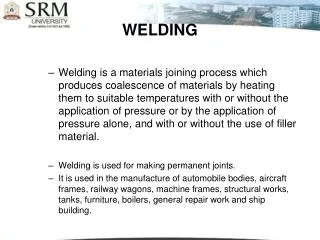
Welding Welding is widely used in fabricating machine parts or other structures that formerly would have been formed by casting or forging. Structural steel frames for buildings, ships, and other structures are often welded. Welding symbols on a mechanical drawing provide precise instructions for the welder. The weld type and the location of each weld must be clearly defined using standardized symbols. CAD libraries of welding symbols can simplify the drawing process. Welding templates can speed the process of drawing by hand.
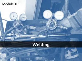
OFW Welding Processes • • Arc welding (SMAW, Shielded Metal Arc Welding, GMAW Gas Metal Arc Welding, plus others…) • • Resistance welding (RSW, Resistance Spot Welding, and others…) • Gas welding (OFW, Oxy Fuel Welding) RSW GMAW An automobile frame is welded on a robotic automobile assembly line. (Courtesy of Vladimir Pcholkin/Stone/Getty images.)
UNDERSTANDING A WELDING SYMBOL A welding symbol added to the drawing has many different features that specify each detail of the weld. The items that can be specified are: • Type of weld • Process • Depth of bevel, size, or strength for some weld types • Groove weld size • Finishing designator • Contour • Groove angle • Root opening • Length of weld • Number and pitch (center to center spacing) of welds • Whether the weld is to be field welded (done on site) • All-around indicator • Which side of the material is to be welded
WELDED JOINTS A number of different types of welds are applicable to each type of joint, depending on the thickness of metal, the strength of joint required, and other considerations. Butt joint Lap joint T-joint Edge joint Corner joint
WELDING SYMBOLS The basic element of the symbol is the “bent” arrow The arrow points to the joint where the weld is to be made Attached to the reference line, or shank, of the arrow is the weld symbol for the desired weld. The weld symbol is placed below the reference line if the weld is to be on the arrow side of the joint, or above the reference line if the weld is to be on the other side of the joint. If the weld is to be on both the arrow side and the other side of the joint, weld symbols are placed on both sides of the reference line.
Supplementary Symbols Fully penetrate A back strap or backing plate is placed onto the back of the joint End the weld at the starting point, or ALL THE WAY AROUND Final contour should be flush (possibly by grinding or machining) Consumable insert is melted into the final weldment Weld at the final construction site (Not in the “shop”) Final contour should be concave (possibly by grinding or machining) Final contour should be Convex (possibly by grinding or machining)
The Welding Symbol Tail Reference to a specification, process, or other supplementary information is indicated by any desired symbol in the tail of the arrow. Otherwise, a general note may be placed in the tail. If no reference is indicated in the symbol, the tail may be omitted. UNLESS OTHERWISE INDICATED, MAKE ALL WELDS PER SPECIFICATION NO.XXX Resistance Spot Weld and an Electron Beam Weld are called out in the Tail of the Welding Symbols.
FILLET WELDS The size of the weld is the length of one leg, For fillet welds on both sides of a joint, the dimensions should be indicated on both sides of the reference line, whether the dimensions are identical or different. .5 Leg lengths Dimensioning of Fillet Welds
Fillet Weld Length and Pitch TWO inch length of weld, with a FIVE inch pitch (center-to-center). The .25 represents the weld leg length. THREE inch length of weld, with a TEN inch pitch (center-to-center). The .25 represents the weld leg length.
Surface Contour and Fillet Welds Fillet weld with a Convex Finish by Machining Fillet weld with a Flush Finish Fillet weld with a Flush Finish by Grinding Fillet weld with a Flush Finish by Chipping Fillet weld with a Flush Finish by Machining KEY: C= chipping G =grinding M = machining R = rolling H = hammering
GROOVE WELDS Symbols and their Result
BACK OR BACKING WELDS A back or backing symbol opposite the groove weld symbol indicates bead-type welds used as back or backing welds on single-groove welds. Back or Backing Weld Symbols
SURFACE WELDS The surface weld symbol indicates a surface to be built up with single- or multiple-pass bead type welds. Because this symbol does not indicate a welded joint, there is no arrow-side or other-side significance, so the symbol is always drawn below the reference line. Indicate the minimum height of the weld deposit at the left of the weld symbol, except where no specific height is required. When a specific area of a surface is to be built up, give the dimensions of the area on the drawing. Surfacing (or Hardfacing) A Plow Blade
PLUG AND SLOT WELDS The same symbol is used for plug welds and slot welds. If it is in the arrow-side member, place the weld symbol below the reference line If it is in the other-side member, place the weld symbol above the line A plug weld is understood to fill the depth of the hole unless its depth is indicated inside the weld symbol
SPOT WELDS The size of a spot weld is its diameter. If you need to indicate the minimum acceptable shear strength in pounds per spot, instead of the size of the weld, place this value at the left of the weld symbol. The pitch would be placed to the right of the weld symbol if needed . .
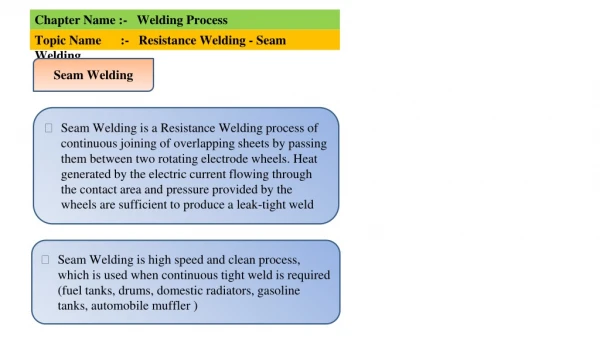
SEAM WELDS The seam weld symbol, with the welding process indicated in the tail, The size of the seam weld is its width. Show this value at the left of the weld symbol, on either side of the reference line. If you need to indicate the minimum acceptable shear strength in pounds per linear inch, instead of the size of the weld, place this value at the left of the weld symbol, and show the length of a seam weld at the right of the weld symbol
PROJECTION WELDS In projection welding, one member is embossed in preparation for the weld. Projection welds are dimensioned by either size or strength. The size is the diameter of the weld.
FLASH AND UPSET WELDS Flash and upset weld symbols have no arrow-side or other-side significance, but the supplementary symbols do. Note that the process reference for flash welding (FW) or upset welding (UW) must be placed in the tail of the symbol.
WELD SYMBOLS FROM CAD Most CAD systems provide a way to quickly generate weld symbols to place in your drawing. SolidWorks Weld Symbol Dialog Box