Download
1 / 32
330 likes | 549 Vues
UNIT - I D.C. GENERATORS. D.C. GENERATORS-CONSTRUCTION & OPERATION DC Generators Principle of operation Action of Commutator Constructional details of DC Machine Types of DC generators EMF Equation. DC Generator. DC motor. D.C. GENERATORS PRINCIPLE OF OPERATION

E N D
UNIT - I D.C. GENERATORS
D.C. GENERATORS-CONSTRUCTION & OPERATION • DC Generators • Principle of operation • Action of Commutator • Constructional details of DC Machine • Types of DC generators • EMF Equation
D.C. GENERATORS PRINCIPLE OF OPERATION • DC generator converts mechanical energy into electrical energy. when a conductor move in a magnetic field in such a way conductors cuts across a magnetic flux of lines and e.m.f. produces in a generator and it is defined by faradays law of electromagnetic induction e.m.f. causes current to flow if the conductor circuit is closed.
Faradays laws First Law : Whenever the magnetic flux linked with a circuit changes, an e.m.f. is always induced in it. or Whenever a conductor cuts magnetic flux, an e.m.f. is induced in that conductor. Second Law : The magnitude of the induced e.m.f. is equal to the rate of change of flux linkages.
Faradays Law of Electromagnetic Induction A changing magnetic flux through a loop or loops of wire induces an electromotive force (voltage) in each loop.
Lenz’s Law “The induced currents in a conductor are in such a direction as to oppose the change in magnetic field that produces them..” OR “The direction of induced E.M.F in a coil (conductor) is such that it opposes the cause of producing it..”
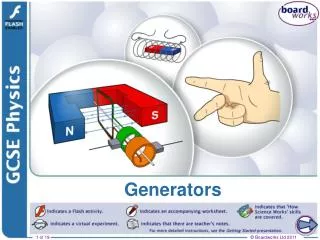
Fleming's Right Hand Rule E.M.F • The Thumb represents the direction of Motion of the conductor. • The First finger (four finger) represents Field. • The Second finger (Middle finger) represents Current
The following are the basic requirements to be satisfied for generation of E.M.F • Magnetic field :- Permanent Magnet (or) Electro Magnet (practical) • Conductor :- Copper (or) Aluminum bars placed in slots cut around the periphery of cylindrical rotor • Relative motion:- By Prime Mover Turbine I.C Engine (Internal combustion) 1.A uniform Magnetic field 2.A System of conductors 3.Relative motion between the magnetic field and conductors
Generators • Basic operation of the generator • As the loop rotates, the magnetic flux through it changes with time • This induces an e.m.f and a current in the external circuit • The ends of the loop are connected to slip rings that rotate with the loop • Connections to the external circuit are made by stationary brushes in contact with the slip rings
Working Principle of D.C Generator Schematic diagram of a simple DC Generator 1st half cycle(00 to 1800 ) Path of current ABR1B1MLR2B2CD 2st half cycle(1800 to 3600) Path of current DCR2B1MLB2R1BA
The output voltage always has the same polarity The current is a pulsating current To produce a steady current, many loops and commutators around the axis of rotation are used The multiple outputs are superimposed and the output is almost free of fluctuations DC Generators, cont
Unidirectional current wave shape Resultant current wave shape when number of conductors used result current wave shape
Constructional Details Of DC Machine • Yoke: • Rotor: • Stator: • Field electromagnets: • Pole core and pole shoe: • Brushes: • Shaft: • Armature: • Coil: • Commutator: • Bearings:
Construction details of DC generator Cross section view of dc machine N shaft S
Interesting, right? This is just a sneak preview of the full presentation. We hope you like it! To see the rest of it, just click here to view it in full on PowerShow.com. Then, if you’d like, you can also log in to PowerShow.com to download the entire presentation for free.