Download
1 / 36
390 likes | 658 Vues
Radar Equations. Radar Equations. Outline Basic Approach to Radar Equation Development Solitary Target Power incident on target Power scattered back toward radar Amount of power collected by the antenna Distributed (Multiple) Targets Distributed (Multiple) Weather Targets.

E N D
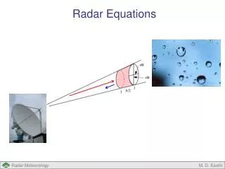
Radar Equations M. D. Eastin
Radar Equations • Outline • Basic Approach to Radar Equation Development • Solitary Target • Power incident on target • Power scattered back toward radar • Amount of power collected by the antenna • Distributed (Multiple) Targets • Distributed (Multiple) Weather Targets M. D. Eastin
Radar Equation Development Basic Approach: Radar Observation: Measurement of echo power received from a target provides useful information about the target (# raindrops ~ reflectivity) Radar Equation: Provides a relationship between the received power, the characteristics of the target, and the unique characteristics of the antenna/radar design Basic development is common to all radars! Solitary Target: Develop radar equation for a single target (i.e., one raindrop) 1. Determine the transmitted power per unit area (power flux density) incident on the target 2. Determine the power flux density scattered back toward the radar 3. Determine the amount of back-scattered power actually collected by the radar Distributed Targets: Expand to allow for multiple targets with the volume M. D. Eastin
Transmitted Power • Isotropic Antenna: • An isotropic radar transmits power equally in all directions • Power flux density at a given range from an isotropic antenna is: • (1) • where S = power flux density (W/m2) • Pt = transmitted power (W/m2) • r = range from antenna M. D. Eastin
Transmitted Power • Directional Antenna: • Most radars attempt to focus all of the transmitted power into a narrow window (a beam) • This is NOT an easy task, but most radars come close • Gain Function: • Gain is the ratio of the power flux density at radius r, azimuth θ, and elevation φ for a • directional antenna to the power flux density for an isotropic antenna transmitting the • same total power: • (2) • Combining (2) with (1): • (3) • In practice, it also incorporates absorptive losses by the antenna and waveguide • The gain function is unique for each radar! M. D. Eastin
Transmitted Power What does the Gain Function look like? 3D Depiction of Gain (dB) Main Lobe Side Lobes M. D. Eastin
Transmitted Power • What does the Gain Function look like? • Main lobe (i.e. the beam) has a maximum • gain of 30 dB • Strongest side lobes are ~4 dB with the • majority less than 0 dB • All back lobes are less than 0 dB • Effective beam width (Θ) defined at • the location equivalent to 3 dB less • than the peak gain on main lobe • (in this case at 27 dB → Θ = 6°) • For the same total transmitted power, • a large peak Gain will correspond to • a narrow beam width → desired 2D Depiction of Gain (dB) M. D. Eastin
Transmitted Power • Relationship between Gain, Beam Width, Wavelength, and Antenna Size? • If the same antenna is used for both • transmitting and receiving, then the • antenna size is related to the Gain • (since the effective beam width is) • (4) • Where: Ae = effective antenna area • λ = transmitting wavelength • Thus: Large antennas → Large Gain • → Small Beam Widths • → Large Wavelengths • Desired: Small beam widths • Small antennas • Large gain 10 cm 0.8 cm M. D. Eastin
Transmitted Power • Problems Associated with Side Lobes: • Echo from the side lobe is interpreted • as being from the main beam, but the • return power is weak because the • transmitted power was weak • Horizontal “spreading” of weaker echo • to sides of storm… M. D. Eastin
Transmitted Power • Problems Associated with Side Lobes: • Echo from the side lobe is interpreted • as being from the main beam, but the • return power is weak because the • transmitted power was weak • Vertical “spreading” of weaker echo • to top of storm… M. D. Eastin
Transmitted Power • Method to Minimize Side Lobes: • Use a parabolic antenna • Parabolic antennas allow for “tapered illumination” • which minimizes the transmitted power flux density • along the edges • Effects of Tapered Illumination: • Reduction of side lobe returns • Reduction of maximum Gain • Increased beam width • The last two are undesirable, but in practice • parabolic antennas reduce side lobes by ~80%, • reduce Gain by less than 5%, and increase beam • width by less than 25% → acceptable compromise Outgoing Power Flux Density Beam Geometry M. D. Eastin
Backscatter Power • Radar Cross Section: • Defined as the ratio of the power flux density • scattered by the target in the direction of the • antenna to the power flux density incident on • the target (both measured at the target radius) • (5) • PROBLEM: We don’t measure Sback at r, • we measure it at the radar • For practical purposes, redefined as the • power flux density received at the radar: • (6) Target Backscatter Power Flux Density Radar Transmitted Power Flux Density M. D. Eastin
Backscatter Power • Radar Cross Section: • In general, the radar cross section • of a target depends on: • Target’s shape • 2. Target’s size relative to • the radar’s wavelength • (more on this later …) • Complex dielectric constant • and conductivity of the target • (more on this later…) • Viewing aspect from the radar M. D. Eastin
Power Received at Antenna • Bringing it all together... • Recall from before: • (3) • (6) • Substituting (3) into (6): • (7) • Accounting for the antenna area: • (8) Power flux density incident on target Radar cross section Power flux density of target backscatter at the antenna Ae is the effective antenna area (m2) Pr is the received power (W) M. D. Eastin
Power Received at Antenna • Bringing it all together… • Recall from before: • (8) • (6) • Substituting (6) into (8): • (9) • Let’s rearrange and examine this equation in more detail… Power flux density incident on target Gain – Antenna size relationship Radar equation for a single isolated target (e.g. an airplane, ship, bird, one raindrop) M. D. Eastin
Radar Equation for a Solitary Target • Written in terms of antenna effective area: • What do these equations tell us about radar returns from a single target? Constant Radar Characteristics Target Characteristics Constant Radar Characteristics Target Characteristics M. D. Eastin
Distributed Targets • Distributed Target: • A target consisting of many scattering elements, for example, the billions of raindrops • that might be illuminated by a single radar pulse • Contributing Region: • Volume containing all objects from which the scattered microwaves arrive back • at the radar simultaneously • Spherical shell centered on the radar • Radial extent determined by the pulse duration • Angular extent determined by the antenna beam pattern M. D. Eastin
Distributed Targets • Single Pulse Volume: • Azimuthal coordinate (Θ) • Beam width in the azimuthal direction • is rΘ, where Θ is the arc length between • the half power points of the beam • Elevation coordinate (Φ) • Beam width in the elevation direction • is rΦ, where Φ is the arc length between • the half power points of the beam • Cross-sectional area of beam: • Contributing volume length = half pulse length: • Volume of contributing region for a single pulse: • (10) M. D. Eastin
Distributed Targets • Single Pulse Volume: NEXRAD Radar • Pulse duration → τ = 1.57 μs • Angular circular beam width → 0.0162 radians • Range from radar → r = 100 km • If the concentration of raindrops is the typical 1/m3, then the pulse volume contains: • 520 million raindrops!! M. D. Eastin
Distributed Targets • Caveats to Consider: • The pulse volume is not a perfect cone • Recall the antenna beam (gain) pattern • About half the transmitted power • fall outside the 3 dB cone • The gain function is not uniform • with the cone – targets along the • beam axis received more power • than those off axis M. D. Eastin
Distributed Targets • Radar Cross-Section: Assumptions • The radial extent (h/2) of the contributing region is small compared to the • range (r) so that the variation of Sinc across h/2 can be neglected • (good assumption) • Sinc is considered uniform across the conical beam and zero outside – the spatial variation of the gain function can be ignored. • (not good, but we are stuck with this one) • Scattering by other objects toward the contributing region must be small so that interference effects with the incident wave do not modify its amplitude • (good for wavelengths > 3 cm) • Scattering or absorption of microwaves by objects between the radar and contributing region do not modify the amplitude of Sinc appreciably • (good for wavelengths > 3 cm) M. D. Eastin
Distributed Targets • Radar Cross-Section: • Equal to the average radar cross for the random array of individual particles that • comprise the target (e.g. average radar cross section of 520 million drops) • (11) • Recall radar equation for a single target: • Radar equation for a distributed target: • (12) M. D. Eastin
Distributed Targets • Radar Reflectivity (ηavg): • Since the radar cross-section is valid for all targets within the contributing volume, • and that volume is non-uniform (i.e. its a function of range and beam shape), we • need to account for this variability in each possible contributing volume: • (13) • Using (13) and the definition of the contributing volume (10), our radar equation • for a distributed target becomes: • (14) M. D. Eastin
Radar Equation for Distributed Targets • Accounting for Gain Function Shape: • Since the gain function maximizes along the beam axis, and decreases with angular • distance from the axis, we can approximate this shape as a Gaussian function • The equation above assumes uniform beam • A correction factor of 1/[2ln(2)] is needed for • Gaussian-shaped beams Radar equation for a distributed target (multiple birds) (multiple aircraft) (multiple raindrops) Radar Characteristics Target Characteristics Constant M. D. Eastin
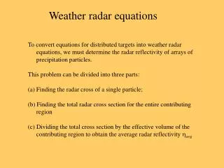
Distributed Weather Targets • Modifying our Radar Equation for Weather Targets: • Since meteorologists are interested in weather targets, we can develop special forms • of the distributed radar equations for typical collections of precipitation particles. • Three tasks must be completed: • Find the radar cross section of a single precipitation particle • Find the total radar cross section for the entire contributing region • Obtain the average radar reflectivity from all particles in that region • First Assumption: All particles are spheres! • Small Raindrops Spheres • Large raindrops Ellipsoids • Ice Crystals Variety of shapes • Gaupel / Hail Variety of shapes M. D. Eastin
Distributed Weather Targets • Second Assumption: All particles are sufficiently small compared to the wavelength • of the transmitted radar pulse such that the back scatter can • be described by Rayleigh Scattering Theory • Types of scattering: • Rayleigh • Mie • Optical • How small? Why Raleigh scattering? • Radius less than λ/20 • Since the particle is much smaller than • the variability associated with the radar • pulse E-field (a sine wave), then we can • assume the E-field across the particle • will be uniform M. D. Eastin
Distributed Weather Targets • Impact of Radar Pulse on a Water Particle: • The radar pulse, and its associated E field, will induce an electric dipole within • any homogeneous dielectric sphere (i.e. a water drop or ice sphere) • The induced dipole vector → Points in the same direction as the pulse’s E field • → Magnitude is the product of the incident field and • the polarization of the sphere: • where: ε0 = permittivity of free space • K = dielectric constant for water/ice • D = diameter of sphere • Einc = amplitude of incident E field • The sphere then scatters that portion of the E field equivalent to the dipole magnitude • The backscatter received at the radar is: • OR M. D. Eastin
Distributed Weather Targets • Radar Cross Section of a Small Dielectric Sphere: • Recall the definition of radar backscatter: • The power flux densities and the E-field are related via: • Using the previous three equations, the radar cross section for a single sphere: Proportional to the sixth power of the diameter Proportional to the inverse fourth power of the radar wavelength M. D. Eastin
Distributed Weather Targets • What is the Dielectric Constant (K2)? • A measure of the scattering and absorption properties of a medium (water or ice) • where: Permittivity of medium • Permittivity of vacuum • Values of K2: • WATER 0.930 (spheres) • ICE 0.176 (spheres) • 0.202 (snow flakes) M. D. Eastin
Distributed Weather Targets • Radar Cross Section of Multiple Dielectric Spheres: • Following the same methods as before: • For an array of particles, we compute the average radar cross section: • We then determine the average radar reflectivity: M. D. Eastin
Distributed Weather Targets • Radar Reflectivity Factor (Z) for Multiple Dielectric Spheres: • Most practitioners of radar use this quantity to characterize precipitation • Thus… • It is regularly expressed in logarithmic units • and displayed on radar screens… Note the required units for Z to have a unitless dBZ M. D. Eastin
Distributed Weather Targets • Radar Equation: • We can then insert our radar reflectivity into our radar equation for a distributed target: • to get our desired radar equation for weather targets: • Solving for Z: Constant Radar Characteristics Target Characteristics M. D. Eastin
Weather Radar Equation • Review of Assumptions: • The precipitation particles are homogeneous dielectric spheres with diameters • small compared to the radar wavelength • Particles are spread through the contributing region. If not, then the equation gives an average radar reflectivity factor for the contributing region • The reflectivity factor (Z) is uniform throughout the contributing region and constant over the period of time required to obtain the average value of the received power • All of the particles have the same dielectric constant. We assume they are all either water or ice spheres • 5) The main lobe of the radar pulse is adequately described by a Gaussian function • Microwave attenuation over the distance between the radar and the target is negligible. • Multiple scattering is negligible. Since attenuation and multiple scattering are related, if one is true, both are true. • 8) The incident and backscattered waves are linearly polarized, M. D. Eastin
Weather Radar Equation Validity of the Rayleigh Approximation: Valid: Invalid: Raindrops: 0.01 – 0.5 cm (all rain) Ice crystals: 0.01– 3 cm (all snow) Ice stones: 0.5 – 2.0 cm (small to moderate hail) λ = 10 cm Raindrops: 0.01 – 0.5 cm (all rain) Ice crystals: 0.01– 0.5 cm (single crystals) Ice stones: 0.1 - 0.5 cm (graupel) Ice crystals: > 0.5 cm (snowflakes) Ice stones: > 0.5 cm (hail and large graupel) λ = 3 cm λ = 3 cm Ice stones: > 2 cm (large hail) λ = 10 cm M. D. Eastin
Weather Radar Equation • Equivalent Radar Reflectivity Factor (Ze): • If one or more of the assumptions built into the radar equation are not satisfied, then • the reflectivity factor is re-named • In practice, one or more of the assumptions is almost always violated, and we • regularly use Z and Ze interchangeably. M. D. Eastin
Radar Equations • Summary: • Basic Approach to Radar Equation Development • Solitary Target • Power incident on target • Power scattered back toward radar • Amount of power collected by the antenna • Distributed (Multiple) Targets • Distributed (Multiple) Weather Targets M. D. Eastin